AeroMentor.nz

Circuit Introduction Notes


Circuit Introduction

The circuit is an orderly pattern used to position the aeroplane for landing and minimise the risk of collision with other aircraft.

Airfields attract aircraft, therefore rules and procedures are required to maintain an orderly sequence or flow of traffic.

Knowing that all aircraft should be following these published procedures makes it easier to identify which runway should be used, where other aircraft are (or can be expected to be), and who has the right of way (or priority) in the sequence to takeoff or land.

Having the right of way does not absolve the pilot-in-command from avoiding a collision.

The standard circuit pattern or procedure, and the rules to be employed around specific aerodromes are published in AIP New Zealand. The rules governing circuit procedures are contained in Part 91, Subpart C.

The skills you have acquired leading up to this lesson combine, so that there is only one new skill to be learnt now – landing the aeroplane.

This briefing is based on the normal left hand circuit, assuming nil wind or at least wind straight down the runway, with variations to this gradually introduced. 

Obviously this will not always be possible, and the briefing will need to be modified for the actual conditions on the day. In addition, discuss with your supervisor or CFI the acceptable weather conditions for this lesson.

Briefing Slides

Considerations


Take-Off Considerations

Even though you will probably have completed a number of take-offs already, this is an important review of what you may know already, but also introduces some new considerations.


Slipstream

In aeroplanes where the propeller rotates clockwise, when viewed from the cabin, the effect of slipstream is to apply a force on the port (left) side of the vertical tail fin, and this will tend to yaw the aeroplane to the left at high power settings. This effect is greatest during the takeoff roll as a result of the high power and low airspeed.

Torque

The effect of torque, the force that tries to rotate the aeroplane rather than the propeller, is to cause increased downward pressure to be applied to the left main wheel. This results in increased resistance on this wheel, yawing the aeroplane to the left.

There are two more effects, but these apply more significantly to tail-wheel aeroplanes.

Asymmetric Blade Effect

Asymmetric blade effect is the result of the down-going blade of the propeller meeting the relative airflow at a higher angle of attack than the up-going blade. This effect is noticeable with tail-wheel aeroplanes; it will only affect tricycle types in the rotate or climb. 

It results in the thrust force being slightly offset to the right (in clockwise rotating engines, as viewed by the pilot) and thus a tendency to yaw to the left.

Gyroscopic Effect

The gyroscopic effect occurs when the tail is raised to the level attitude. This causes a force to be applied to the propeller disc, the effect of which will be to produce a turning moment, which acts at 90 degrees in the direction of propeller rotation. Gyroscopic effect has no practical application to tricycle types.

Keeping Straight

You must remember that rudder should be used as required to keep the aeroplane straight during the take-off roll by reference to a feature at the far end of the runway, and if available, the runway centreline. Whenever power is changed the aeroplane will yaw, and must be corrected with rudder.

Crosswind

The tendency for the aeroplane to weathercock (point nose into wind) during the ground roll or while taxiing, as a result of a crosswind pushing on the empennage is explained, and the need to keep straight on the reference point is restated. In the air, allowance for drift is necessary to track towards any reference point.


Headwind

The presence of a headwind reduces the length of the ground roll and in an extreme example, if the aeroplane was parked facing into the wind, and the wind was blowing at ** knots, the aeroplane would be about to get airborne, and they sometimes do in strong winds if not tied down well.

There will be no drift experienced if the wind is directly ahead of the aeroplane, and there is no crosswind component.


Tailwind

A takeoff with the wind would require the aeroplane to be accelerated to the wind speed just to bring the airflow over the wing to a standstill, – a further ** knots would be required to get airborne, greatly increasing the takeoff distance required, for example, just 5 knots of tailwind increases take-off distance by 30 percent.

Taking off with a tailwind results in a shallow angle of climb, reducing obstacle clearance.


Landing Considerations

Climb Angle

If the wind was blowing at 70 knots and the aeroplane was in a 70-knot climb, to a ground observer the aeroplane would appear to rise like an elevator, as the distance travelled forward over the ground would be zero. Therefore, the angle of climb is increased (ie, is steeper) into wind, improving obstacle clearance.

Takeoff into Wind

For the above reasons, all takeoffs are into wind, to minimise the ground roll and takeoff distance, and to improve the climb angle.

Ground roll = 
brake release 
to liftoff.
 both are affected
Takeoff distance =
distance taken 
to achieve height 
of 50 feet.

Power

Use full power to minimise the takeoff roll and ensure climb performance.

Flap

Flap increases lift and drag. Because of the drag increase, most light aeroplane Flight Manuals do not recommend the use of flap for a normal takeoff, although this will depend upon the runway surface.

Surface and Slope

Discuss factors that are applicable to the runway being used.

Landing

Wind

Landing into wind reduces the ground speed, requiring less stopping distance, and therefore a shorter landing distance and ground roll.

Ground roll = 
wheels-on-the-ground 
distance.
 both are affected
Takeoff distance =
from 50 feet above 
threshold to full stop.

Once again if the headwind is 70 knots the aeroplane would not need to move forward at all to descend at 70 knots. Therefore, a headwind steepens the approach and improves obstacle clearance.

Flap

Flap increases lift and drag. The increased lift lowers the stall speed and permits a lower and safer landing speed, which will also reduce the ground roll. The increased drag allows a lower nose attitude for the same airspeed, and it increases the rate of descent, steepening the approach which provides improved forward visibility and obstacle clearance.

Power

Power controls the height or rate of descent. As discussed in the Climbing and Descending lesson, increasing or decreasing the power alters the rate of descent.

The increased rate of descent as a result of using flap is countered by the use of power to control the rate of descent. In addition, the use of power provides a slipstream effect that makes the rudder and, more significantly, the elevator more effective. Therefore, in a modern light aeroplane the normal approach is a powered approach using full flap. The various reasons for limiting flap during the approach will be discussed under the non-normal circuits.


Brakes

Brakes will need to be used to either slow the aeroplane or bring it to a stop. If carrying out a touch and go, brakes will not be used.

It is very important that you need to keep your feet off the toe brakes to avoid inadvertent use of the brakes during takeoff or landing.


Runway Length

You should be in no doubt that sufficient runway length for takeoff and landing must be available before starting the takeoff or approach.

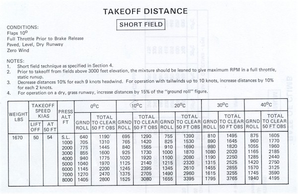
At this point you should have carried out the necessary calculations. However, before the third or fourth (refer CFI ) revision exercise of circuits, a formal briefing or discussion of the Group Rating System and its application should be given. Before the fifth or sixth (refer CFI) revision of circuits, the calculation of takeoff distance by reference to the Flight Manual should also be carried out.

The effects of density altitude, weight, surface and slope are discussed during circuit revision when discussing calculation of required takeoff and landing distances. Therefore, you need not be formally introduced in this briefing, unless anything is pertinent to your normal circuit (refer CFI). The effect of these factors will be revised (not taught) during the briefing Short Field Takeoffs and Landings.

Wind Shear

The effects of wind shear may be discussed (refer CFI) or incorporated in the second lesson on circuits.


Supplementary Considerations

Airmanship

Throughout circuit training you should place more and more emphasis on command decision making.

Checklists

Checklists, as well as the use of a kneepad to record ATIS (Automatic Terminal Information Service) information, fuel endurance and clearances, will assist in the retention and processing of information.

It is well known that humans are limited in their ability to recall information accurately from memory. The use of written checklists for normal and emergency operations is reasonably common in general aviation. However, basic flight training still tends to use mnemonics exclusively for all operations. What is learnt first is generally accepted as being the correct method, therefore, the use of checklists should be encouraged during basic training.

There are two ways to use a checklist. It can be a list of things to do, as used with complex aeroplanes or systems, or a list to check off things that have been done, as used with simple aeroplanes or systems. General aviation basic training tends to use mnemonics to complete the checks, while confirming that checks have been completed by using a written checklist.

Correct use of the aeroplane radio and checklists will influence situational awareness.

Right-of-Way Rules

As there will be several pre-flight briefings during circuit revision, the right-of-way rules can be spread over these briefings.

The suggested rules for discussion in this briefing are:

  • aircraft taking off and landing have right of way over all other traffic,
  • aircraft landing have right of way over aircraft taking off,
  • aircraft established in the circuit have right of way over joining traffic,
  • the good aviation practice considerations of avoiding overtaking or cutting in, and
  • the application of the right of way rules while taxiing.

The rules or good aviation practice considerations most pertinent to your operation should be considered first, for example, circuit direction and altitude.

Aeroplane Management

The importance of normal instrument readings is revised.

SADIE checks are introduced

Suction

gauge is operating in the green range.

Amps or Alternator

is functioning correctly.

Directional Indicator (DI)

has been synchronised to the compass and is functioning correctly.

Ice

existence of carburettor ice has been checked for and the carburettor heat applied if required.

Engine

temperatures and pressures are in the green range.


Human Factors

Good communication (radio, ATIS), pre-flight / in-flight planning and regular practice will minimise disorientation. In addition you should be asked to describe the wind direction and strength to help orientate yourself.

Visual landing cues are introduced in this lesson, and the various aspects of visual limitations previously discussed should be revised.

During circuit training there is a possibility you may reach a learning plateau, where progress may appear to be minimal, discuss this with your instructor if it happens.

On the downwind leg, although the physical eye height will vary, the effect on the judgement of spacing will be negligible. 


The Flight

Air Exercise

One method you may like to use, is to draw the circuit pattern and number and identify the various points around the circuit at which the listed actions are carried out.

Since each lesson leading up to the circuit involved one or more legs of the circuit, this lesson is primarily revision and application, with emphasis on the new material – the landing.


Take Off

Takeoff

Only the main points are revised, for example, reference points, keeping straight and rotate speed if applicable, as you will probably be doing the takeoff by now.

Two reference points should be chosen on lining up (backed up by the DI), one at the far end of the runway on which to keep straight during the takeoff roll, and one higher up to keep straight on during the climb.

This second reference point may need to be modified, if a crosswind is present, to prevent drift and provide a straight track over the ground along the extended centreline.

On lining up, the aeroplane should be allowed to roll forward a short distance on the centreline to ensure the nosewheel is straight and aligned with the centreline.

Once on the runway the aeroplane is held on the foot brakes (if required), never on the park brake. When taxiing, forgetting to release the park brake is easily and rapidly identified, however, with the application of full power for takeoff, the poor acceleration may not be recognised early enough.

In aeroplanes fitted with only a hand-operated brake, if the brake is applied once on the runway, the hand applying it should not be removed until the brake is released.

Early in the takeoff roll, with full power applied, temperatures, pressures, rpm and airspeed should be checked for normal readings.

During the normal takeoff, the aeroplane is seldom actually rotated. Common practice is to use elevator back-pressure to take the weight off the nose-wheel as the aeroplane accelerates. The aim is to reduce the loads on the nose-wheel (the undercarriage weak link) and reduce friction. As the aeroplane continues to accelerate it will fly off in a slightly nose-high attitude and rapidly accelerate to the nominated climb speed.

‘Rotate’ generally refers to rotating the aeroplane about its main wheel axles into a nose-high attitude to increase the angle of attack and lift the aeroplane off the ground. Commonly this is done at a speed just above the stall speed (about 5 to 10 knots). The aim of this procedure is to minimise the retarding effects of the ground roll, and is often used on soft surfaces or on runways of minimum length. There may, however, be an appreciable delay in accelerating to climb speed.

Maintain the appropriate pitch attitude until reaching the nominated climb speed, and then hold the climb attitude and trim.

Climb Out

Each leg of the circuit is named and explained. The first leg – climb out – is the leg on which separation from other aircraft in the circuit is achieved. This is because the aeroplane groundspeed is at a minimum while climbing into wind, and therefore the circuit pattern is minimally distorted. 

The practice of trying to provide adequate separation from aircraft ahead during the downwind leg, where the groundspeed is at a maximum, should be discouraged as this tends to unnecessarily stretch out a busy circuit. Therefore, although a climbing turn onto crosswind may be started at 500 feet AGL, the actual height at which the turn is started will be dictated by traffic ahead.

Where no conflict with traffic ahead is anticipated, the turn should be started at 500 feet AGL – this will assist any following aircraft. Ensure an appropriate lookout is conducted, and reference point identified.

During the climb out and at a safe height, not less than 300 feet AGL, the after takeoff checks are completed. A check is made (glance back) to confirm whether the chosen high reference point is maintaining the aeroplane along the extended centre-line. If not, an adjustment to the chosen reference point is made.

If flap is used, retraction heights and speeds need to be discussed.

At night runway heading (DI) is maintained to avoid spatial disorientation.


Crosswind

Crosswind

The cross-wind leg is at 90 degrees to the climb out path and in the circuit direction. Before starting the turn, lookout is stressed and a reference point onto which to turn is chosen.

Commonly, this is a point on the horizon off the wingtip. However, since the aim is to track over the ground at right angles to the runway, the reference point will need to be modified to allow for drift.

Downwind

Downwind

For many situations the turn onto downwind is made when the aeroplane is at 45 degrees to the upwind threshold, onto a suitable reference point so as to track parallel to the runway, and the aeroplane is levelled at circuit altitude. This may require the aeroplane to be levelled before, during or after the turn onto downwind. Lookout is again stressed, especially for aircraft joining the circuit on the downwind leg.

The downwind radio call is given abeam the upwind end of the runway to positively establish your position in the circuit for other traffic and Air Traffic Control (ATC) if applicable. If the radio call is delayed for any reason until abeam the threshold, or later, the call should be “late downwind.” As a common courtesy, and to promote situational awareness for all traffic in the circuit, the downwind call should include your intentions, for example, full stop or touch and go. 

If your position in the circuit is advised by ATC, for example, “number three”, a visual search must be made to positively identify the positions of the appropriate number of aircraft ahead. This is generally achieved by scanning from the threshold back along the approach path and base leg, counting off aircraft sighted, ahead of you.

Checklists

The attempt to standardise checklists across aeroplane types may result in irrelevant checks becoming so automatic that they are not actually carried out when required. Latent errors do exist within checklists, and it is recommended that the normal checklist be type-specific and backed up by a written checklist (refer CFI).

Thus the use of BUMFH is considered irrelevant for fixed-undercarriage types and generally wrong for retractable types. Most aeroplanes with retractable gear require the undercarriage to be extended before the brakes can be checked for pressure. So the mnemonic should be UBMFH when flying aeroplanes with retractable undercarriage.

The pre-landing checks are:

Undercarriage

Down and locked (If your organisation includes it at this stage for consistency with later training.)

Brakes

Pressure checked, and park brake off

Mixture

RICH

Fuel

On the fullest tank, fuel pump ON (if applicable) and pressure checked

Harnesses and Hatches

Secure and doors or canopy closed

Spacing

To judge spacing, a feature of the air-frame is assessed against the runway; for example, in most low-wing aeroplanes the correct spacing is achieved when the wingtip runs down the centre-line, as observed by left hand seat (for a left hand circuit). 

In the PA 38, which has very long wings, the outboard flow strip is used, and in high wing aeroplanes the spacing is normally one third of the way down the wing strut from the tie-down end. This can be difficult for people to see, and there may be some value in marking the strut with tape or a felt-tip pen at the approximate position on the strut through which the runway should cut.

The spacing should be assessed and then corrected at the base turn, allowing for any drift. Do not weave downwind in an effort to correct the spacing. The reference point may be altered in order to maintain a parallel track to the runway. In nil wind the DI should show the reciprocal of the runway in use.


Base

Base Turn

The turn onto base starts at approximately 45 degrees to the threshold. Emphasise the lookout and choose a reference point off the wingtip. Carburettor heat is selected ON, power reduced and a level turn started to bring the airspeed into the white arc. Once in the white arc, 10–20 degrees of flap is selected and, as the airspeed approaches the nominated descent speed, the correct descent attitude is selected, held and trimmed.

The power setting chosen at the base turn depends on the assessment of the downwind spacing (close, correct or wide) and the proximity to 45 degrees from the threshold when starting the turn (early, correct, late). Commonly, 1500 rpm is used as a guide, and this is based on the correct spacing downwind and 45 degrees to the threshold. Any other condition will require a higher or lower power setting; for example, close downwind but correct at 45 degrees, try a lower power setting, say 1300 rpm.

The turn is continued onto the reference point with an allowance for drift or until the leading edge of the wing or wing strut is parallel with the runway (allowing for drift).

Avoid using ground features as turning reference points as this may cause difficulty at an unfamiliar aerodrome.

Base Leg

Once established on base leg additional flap is extended and the attitude adjusted to maintain the nominated approach airspeed.

At the base turn, you should be encouraged to estimate what power setting you would require, to get to the threshold in a steady descent without any changes. This does not mean that the power setting should not be altered if required.

Before the descending turn onto final, emphasise the lookout, especially along the approach path to ensure no other aircraft are on long final. The roll out onto final, or approach leg, must be anticipated so that the wings are level at the same time as the aeroplane is aligned with the centre-line. Throughout the turn the angle of bank should be adjusted to achieve this by about 500 feet agl. The nominated approach airspeed should be maintained by adjusting attitude.

During the approach, as with all phases of flight where the intent is to maintain a specific airspeed, it is important to emphasise that the correct attitude, for the desired airspeed, should be selected, held and trimmed.

Attitude controls the airspeed

Final

Final

When established on final, full flap is selected at the appropriate time and the airspeed maintained, or allowed to decrease to threshold crossing airspeed through attitude adjustment (refer Flight Manual and CFI).

Because of the possibility of large flap deflections and the aeroplane’s low altitude, extending flap during the turn onto final is avoided.

The approach path is monitored by reference to the correct runway perspective. Throughout the descent the aiming point, commonly the runway numbers or threshold, is monitored and the power adjusted as required to maintain a steady rate of descent to touchdown.

Power controls the rate of descent

With the aeroplane trimmed to maintain the required attitude (airspeed), if the aiming point moves up the windscreen, the aeroplane is undershooting – increase power. If the aim point moves down the windscreen, the aeroplane is overshooting – decrease power. If the aeroplane is correctly trimmed the power adjustments will be quite small; these are often described by the term “a trickle of power.”

On short final in anticipation of any requirement for full power, carburettor heat is selected COLD when a landing is assured.


Landing

Landing

The landing is one smooth manoeuvre designed to slow the rate of descent to zero and the speed to just above the stall speed, as the wheels touch the ground. This manoeuvre consists of two phases, the round-out and the hold-off, also known as the flare. 

This is essentially a progressive transition from a descent into a flared landing attitude, similar to a power-off stall, with touchdown just before the moment of stall.

The round-out begins at a suitable altitude for the aeroplane’s speed. For a normal approach this is described as about 50 feet.

When the landing is assured, often pattered as “crossing the fence”, the throttle is closed, and at about 50 feet the nose attitude progressively raised – the round-out. As the airspeed decreases the aeroplane will start to sink. The sink is observed by looking outside at the far end of the runway (or horizon) and this is the point where the second phase of the landing process begins. The most common errors made by students during the round-out is not looking far enough ahead and lowering the nose in an attempt to fly down to the ground.

The hold-off involves a gradual increase in back-pressure to control the rate of sink and to achieve the correct attitude so that the touchdown is light and on the main wheels only. During this phase your focus is gradually shortened to facilitate depth perception and provide cues about the sink rate until, at touchdown, the point of focus is just ahead and slightly left of the aeroplane’s nose.

Following touchdown on the main wheels, the nose-wheel should be gently lowered with elevator by relaxing the back-pressure and lowering the nose onto the runway.

Keep straight on the runway centreline with rudder, by reference to a point at the far end of the runway, normally the end of the centre-line, and apply brakes as required.

Under ideal conditions, during your introduction to the circuit, each circuit is flown to a full stop and the aeroplane taxied to the holding point for another takeoff. Therefore, the considerations of a touch and go and the go-around are deferred to the next circuit lesson – Circuit Considerations.

Although including the go-around in this briefing can generally be deferred, it is not always convenient in a busy circuit to carry out full-stop landings. Therefore, a brief discussion on the touch and go procedure may need to be included in this briefing (refer CFI).

Should a go-around be required during this introductory exercise, it is recommended that you are guided through the procedure.

The after-landing checks are normally completed clear of the runway.


Air Exercise

On the Ground

You should be capable of taxiing to the appropriate holding point and carrying out at least some of the checks and using the checklist. Try to complete a take-off safety (or emergency) brief.

The Exercise

Start by receiving a demonstration of an ideal circuit, followed by a pattering circuit.

You should be able to fly almost all of this exercise, but will probably still need help with the landing. Try to fly as much as possible – you will only learn by doing, and you must be able to do it consistently for yourself before you can go solo.

Your instructor will need to talk you through most of this exercise, but as the circuit lessons progress you will find your instructor saying less and less.

After Flight

You should be reassured that even though there seems to be a lot to fit into the circuit, there will be plenty of opportunities to get it right, as all of the following lessons to first solo will be in the circuit.

Continue to be enthusiastic about learning the ground checks, and to start learning the pre-landing checks.

During circuit revision, your supervising instructor will regularly fly with you, to monitor your progress and provide feedback on your flying.

Throughout circuit revision, formal briefings or guided discussions will be required to ensure that all environmental factors affecting taxiing and the circuit have been learnt before a solo check flight.

Remember to check English language requirements are met well before your first solo is considered.


How

Before take off 

Taxi and holding point procedures 

Airmanship considerations 

Checks 

Radio calls and clearance 

Line-up on runway with headwind

Feet clear of brakes 

Select feature for reference

Ensure nose-wheel is aligned straight with centre-line 

During take off

Open throttle smoothly to full power

Use rudder to maintain centre-line 

Apply slight back pressure on control column 

Note RPM, oil temp and pressure, fuel flow and ASI (air speed indicator)

At lift-off speed, use smooth and positive back pressure on control column to achieve lift-off

After take off

Note initial pitch attitude

Maintain lateral level and heading

When desired rate of climb speed is reached, re-adjust pitch to maintain speed

Trim aircraft to maintain attitude 

Maintain lookout above and below as well as side to side 

At 450-500 feet, lookout and roll into crosswind leg 

Allow for drift and level aircraft to straight and level at circuit height 

Maintain visual lookout and listening watch

Medium turn onto downwind and fly parallel with runway 

Downwind

Downwind checks and radio calls

Maintain lookout, circuit altitude and position relative to runway

Base leg

Lookout

Reduce power with carb heat (if outside green range)

Select flap when in flap range 

Maintain altitude until descent speed is reached

Lower nose to maintain descent speed 

Trim to hold attitude

Medium turn onto base leg 

Use power to adjust rate of descent

Use attitude to control speed

At 500-600 feet AGL, anticipate turn onto final and align with centreline 

Landing

Maintain descent speed all the way down to the ground

Just above runway commence round-out and reduce power to idle

Look to the end of runway, and maintain centreline 

As airspeed slows, continue to pull back on the control column, flying just above the runway

Maintain direction with rudder

Just before the wheels touch down, continue to pull back on the control column to ensure the main wheels touch down first

Once on the ground, continue to pull back and gently put the nose wheel on the ground

Once aircraft slows to a fast walking pace, taxi clear of runway and make appropriate radio calls 


Common Mistakes

Mistakes other people make flying circuits

You will be unable to display a high standard of airmanship during the initial stage of practising this exercise, due mainly to the workload involved. Whereas this must be accepted in the early stages, it will become unacceptable as your experience and competence to handle the aircraft increases. 

The necessity for you to make firm and confident decisions during this exercise is paramount, and it is only after you have developed this capability that you can be considered for solo flight. A common error while practising approaches is to neglect to monitor the altimeter during the base leg after approach power has been initially selected. This often results in being too low or too high at the position for the final turn. 

Ensure you understand from the beginning that the power selected at the key position is not a standard RPM, but will need to be varied according to the distance out from the touchdown area and the strength and direction of the wind. This latter item is particularly important during crosswind landings, when head or tailwind components will be experienced on the base leg. 

Failure to commence the turn onto final approach at the correct moment or not varying the bank angle as required to position on the extended centreline as the turn is completed, are quite common errors. Because of the effect of delaying a settled approach path, these errors need to be overcome as soon as possible. 

A good landing is more likely to occur from a good approach. General difficulties and random errors during landings are often the result of inaccurate or badly executed approaches. Correct speeds and early use of power are very important. If the airspeed is allowed to wander more than a few knots the nose attitude will have changed, resulting in a misleading impression of the landing path position relative to the engine cowling and windscreen. 

This will often give the impression of being too high or too low when the descent path is actually correct or, alternatively masking a needed alteration of power. Your failure to round out early enough, or rounding out and holding off too high can usually be corrected by approaching a little faster than normal, so that you can prolong the round out, holding off to allow yourself more time to become accustomed to the appearance of the ground and the aircraft attitude up to the point of touchdown. You should only be demonstrated and try this with an instructor onboard. 

Many students commence to hold off, but then discontinue the backward movement of the control column. This fault is often overcome by flying the aircraft slowly just above the ground, demonstrating that the elevators remain effective and that the control column should be moved as much as necessary to hold the main wheels off the ground to the point of touchdown.

Most pilots over the age of 40 need spectacles to correct their vision for reading. Some will in addition need correction for distant vision and a number will need correction for vision at instrument panel range. The wearing of correct spectacles which are suitable for flying is therefore very important.

Where the only correction necessary is for reading, pilots should never use full-lens spectacles whilst flying, because the pilot’s task requires frequent changes from near to distant vision and the latter will be blurred by reading glasses. The use of incorrect glasses for the task can often cause difficulty during landing, and the instructor should ensure that where spectacles are being worn by a student they are of the correct type.

Having landed successfully, a student may have difficulty in controlling direction during the landing run. This is often due to premature relaxing of his concentration, or diverting his attention to cockpit workload, R/T calls etc. Remember that habits once formed are difficult to overcome, and although the maintenance of direction immediately after landing may be relatively easy in gentle winds, or into wind landings, this will not be so during those occasions when a strong crosswind is prevailing. 

Any diversion from the maintenance of heading and aircraft control during the landing roll in this type of situation could become hazardous. Therefore, you should be taught a habit which will stand you in good stead for all circumstances, and in this case one which consists of handling R/T calls only after the aircraft has slowed right down, and carrying out the after-landing checks when the aircraft is stationary and clear of the landing path.

Slow Flight Notes


Slow Flight Notes

There are a number of situations when the aeroplane must be flown at or near its minimum airspeed, for example, during takeoff, landing, a go around, or missed approach and in the stalling lessons.

This lesson is not for operational slow flight, but aims to improve your awareness of the characteristics of flight at slow airspeeds and provides practice in maintaining balanced flight at those airspeeds. It is another important coordination exercise, reinforces the lessons learnt during Straight and Level at varying airspeeds, and is good preparation for the stalling lessons and for the takeoff and landing phase of circuit training.

Briefing Slides

Considerations

Objectives


To slow the aeroplane and maintain straight and level at low airspeed (1.2VS).

To maintain straight and level at low airspeed in various configurations.

To maintain a constant altitude while turning at low airspeed.

To return to normal operating airspeeds.


Principles of Flight

In normal cruise the angle of attack was approximately 4 degrees and the airspeed ** knots.

From the Straight and Level lesson, lift is primarily controlled by varying either angle of attack or airspeed. As lift must equal weight to maintain level flight, as the airspeed decreases the angle of attack must increase.

Power + Attitude = Performance

In order to fly level at lower than normal airspeed, a higher than normal nose attitude is required, and once at that attitude, a small increase in power is needed to maintain the desired altitude.

Revise control effectiveness at slow speeds and the effects of slipstream. The controls will be sluggish and not as responsive as they would be at a higher speed and the reduced slipstream will require balancing with rudder.

Revise the effect of low airspeeds on control input and response. As was seen in the turning lesson a slower speed produces more adverse yaw.


Supplementary Considerations

Airmanship

Revise the 20 degree visual scan technique as introduced in the Medium, Climbing and Descending Turns lesson. Take into account the high nose attitude.

HASELL checks are carried out before stalling and aerobatics, and are introduced in this lesson.

Height (not altitude)

Not less than 2500 feet above ground level.

Some organisations stipulate a height greater than 2500 feet agl, consult with your CFI.

Airframe

State the configuration to be used.

Security

No loose articles, harnesses secure.

There should be no loose articles in the cockpit at any time because of the potential for jammed controls. Explain that harness security is a good aviation practice consideration.

Engine

Temperatures and pressures normal, mixture rich, fuel sufficient and on fullest tank. Fuel pumps operated in accordance with operator procedures.

This is a routine systems scan to ensure everything is normal, before and during the exercise.

Location

Not over a populated area and clear of known traffic areas, including airfields.

Lookout

Carry out a minimum of one 180-degree, or two 90-degree, clearing turns, to ensure other traffic will not result in conflict.

Aeroplane Management

The use of smooth but positive throttle and control movements should be stressed. Even though more positive movement of the controls will be required there is no need to be aggressive with the controls.

Revise why carburettor heat may need to be used.

Be aware that operating at low airspeeds may raise engine operating temperatures.

Consider the position of the aeroplane three dimensionally within the training area.

Consider the warning symptoms of the approaching stall and be constantly aware of the aeroplane’s configuration and flight phase.


Human Factors

There is a high level of concentration needed in this exercise, and is therefore quite a demanding lesson.

The high nose attitudes will be unfamiliar initially.


The Flight

Air Exercise

Straight and Level at Low Airspeed

Using the flight manual, or by conducting a stall, determine 1.2VS

A reference altitude is nominated and a reference point selected.

Power + Attitude = Performance

Power

Is reduced (carburettor heat may be required) to approximately  rpm.

The resultant pitch change and yaw must be compensated for. Ensure smooth throttle movements are used.

Attitude

With the elevator, adjust the attitude to maintain level flight.

The airspeed will decrease gradually. As the airspeed decreases the aeroplane’s nose will want to pitch down, requiring subtly increasing back pressure on the control column to maintain the altitude. The wings should be kept level in relation to the horizon, and rudder adjusted to keep straight on the reference point.

Remind yourself that during those phases of flight where power and/or airspeed are changing, a change in rudder pressure will be required to maintain balance.

Trim

Promptly and accurately.

Maintain straight and level flight at the nominated airspeed, adjust power as necessary to maintain height and apply the mnemonic LAI.

Lookout

In a scan loop, look out to the left (port) and scan 20 degrees for 2 seconds from left to right, passing over the nose of the aircraft.

Attitude

Ensure the attitude is correct and, more importantly, constant. When the outside scan is complete, scan inside.

Instruments

The instruments are scanned to confirm accurate flight.

If a constant altitude is not being maintained, use power as required and adjust attitude to maintain the nominated airspeed.

Power + Attitude = Performance.

If the correct level attitude has been selected the airspeed will be ***  knots (as nominated).

If the correct power setting is maintained the aeroplane will maintain level flight, and if the wings are level and balance maintained the aeroplane will remain straight.


Turning at Low Airspeed

Lift will need to be increased in the turn and this will produce an increase in drag. Power will need to be increased to combat the drag and maintain the nominated airspeed.

Revise adverse yaw from the Medium, Climbing and Descending Turns lesson. Adverse yaw is countered with rudder applied in the direction of the roll, maintain balance.

At low airspeeds the ailerons will need to be deflected further to achieve the same roll rate as at higher airspeeds. This will significantly increase the induced drag and require more rudder to negate the adverse yaw.


Returning to Normal Cruise

To regain normal cruise, the mnemonic PAT is used. Because of inertia, power leads the sequence to arrest any descent resulting from lowering the attitude.

Power

Carburettor heat COLD (if applicable), and smoothly increase power to full power.

Correct the resultant yaw with rudder and the pitch up with elevator while:

Attitude

Gradually lowering the nose and holding the level attitude. Maintain wings level with aileron, and balance with rudder (as airspeed increases).

Trim

Remove obvious loads. When flaps have been raised (if applicable) and normal cruise airspeed achieved, set cruise power, and confirm straight and level is maintained. 

Trim accurately to hold the correct attitude.

LAI scan

On the Ground

Carry out a thorough preflight inspection under the supervision of your instructor.

Try and start to do more radio work and using the checklist


The Exercise

You should be able to complete the takeoff by yourself by this stage.

On the way out to the training area, there is opportunity to practise climbing and turning.

Enter straight and level from the climb and talk through the HASELL checks.

Practice the entry to slow flight at the nominated airspeed and in the nominated configuration – with and without flap. 

Demonstrate turning (at up to 20 degrees angle of bank) including reversing the turn direction.

Try to regain normal cruise, while talking through the process.

Establish the aeroplane in the approach configuration in a descent at 1.2VS. Then establish the aeroplane in a climb, thereby simulating the go around.

On the way back to the aerodrome, discuss some more radio calls and rejoining the circuit.


After Flight

The next lesson will be Basic Stalling, make sure you read up on this.

Find a copy of the checklists and start learning the correct responses for the checklist items. You should be starting to know the checklists from memory, which is necessary before you do your first solo flight, and the first step to memorize them is to learn the correct responses.


Level flight

Estimate power required for flight (Vs1 + 10kts)

Reduce power, adopt attitude and trim 

Re-adjust attitude and power as required

Maintain altitude, heading and balance 

Altitude change corrected by power change 

Climbing 

Nominate climb rate or speed

Gradually increase power to full power whilst maintaining airspeed, heading and balance

Stabilise power when climb rate or speed is reached 

Re-trim

Turning

Maintain lookout

Roll into medium turn and increase power 

Maintain balance with rudder

Increase power to maintain altitude  and speed

Descending

Nominate rate of descent or speed

Maintain lookout below and side to side 

Reduce power to set descent rate or speed

Set descent attitude to maintain speed

Trim to reduce control pressures 

Straight and Level

Air Exercise

Straight and Level at Low Airspeed


Using the flight manual, or by conducting a stall, determine 1.2VS

A reference altitude is nominated and a reference point selected.

Power + Attitude = Performance

Power

Is reduced (carburettor heat may be required) to approximately  rpm.

The resultant pitch change and yaw must be compensated for. Ensure smooth throttle movements are used.

Attitude

With the elevator, adjust the attitude to maintain level flight.

The airspeed will decrease gradually. As the airspeed decreases the aeroplane’s nose will want to pitch down, requiring subtly increasing back pressure on the control column to maintain the altitude. The wings should be kept level in relation to the horizon, and rudder adjusted to keep straight on the reference point.

Remind yourself that during those phases of flight where power and/or airspeed are changing, a change in rudder pressure will be required to maintain balance.

Trim

Promptly and accurately.

Maintain straight and level flight at the nominated airspeed, adjust power as necessary to maintain height and apply the mnemonic LAI.

Lookout

In a scan loop, look out to the left (port) and scan 20 degrees for 2 seconds from left to right, passing over the nose of the aircraft.

Attitude

Ensure the attitude is correct and, more importantly, constant. When the outside scan is complete, scan inside.

Instruments

The instruments are scanned to confirm accurate flight.

If a constant altitude is not being maintained, use power as required and adjust attitude to maintain the nominated airspeed.

Power + Attitude = Performance.

If the correct level attitude has been selected the airspeed will be ***  knots (as nominated).

If the correct power setting is maintained the aeroplane will maintain level flight, and if the wings are level and balance maintained the aeroplane will remain straight.


Common Mistakes

Mistakes other people make during slow flight

Students will normally tend to concentrate on the airspeed which in one sense is beneficial, but as the object of the total exercise is complete control over airspeed, altitude, heading and balance you must learn to scan the various instruments whilst also maintaining a careful lookout. 

In this respect it should be pointed out that once the correct power setting has been achieved, the maintenance of a constant altitude will also result in a constant airspeed, unless the aircraft is allowed to become unbalanced or updraughts/ downdraughts are present.

Balance, particularly when the aircraft is being flown at high power and low airspeed will create a much larger problem than when the aircraft is being flown at normal operational speeds, and it may be necessary in the early stages for the instructor to fly the aircraft in relation to pitch and lateral level and leave the student the single task of maintaining balance by use of the rudder.

Students must be given the opportunity of learning how to control yaw at speeds approaching the stall. The few seconds spent during normal stall practice are not sufficient for this purpose. In conclusion it could be correct to say that training in spin prevention begins with training in the exercise of ‘slow flight. 

There is no doubt as to the importance of this practice and the opportunities to do it during a 40 hour course are plentiful.

If students are taught to safely control the aircraft whilst maintaining pre-selected altitudes and headings at low airspeeds whilst keeping the aircraft in balance, they will have obtained a greater insurance against entering an inadvertent stall/spin than by practising many actual recoveries from developed stalls.

Basic Stalling Note


Basic Stalling Note

The Slow Flight lesson has been introduced andthe practice of flying close to the stall. Here you are furthering your knowledge by showing how the aeroplane behaves when there is not enough lift produced by the wings to balance its weight.

Many new terms and concepts will be introduced during this briefing, and these should be kept as simple as possible.

When an aeroplane stalls, it is not like a car – the engine does not stop. The stall is a breakdown of the smooth airflow over the wing into a turbulent one, resulting in a decrease in lift. The lift will no longer fully support the aeroplane’s weight, and the aeroplane sinks.

For the basic stall we keep the aeroplane’s configuration as simple as possible, power will be at idle, flap will be up, and if the undercarriage can be raised, it is.

There are three reasons why pilots needs to know about stalling. The first is so they can avoid the inadvertent stall. The stall does not just happen – there are many warning signs of its approach, and you should be familiar with these.

To prevent the inadvertent stall a pilot needs to be able to recognise the symptoms of an approaching stall, experience it, and then learn the correct recovery technique.

The second reason for being familiar with the stall was highlighted in the last lesson, Slow Flight. There are a number of times an aeroplane will be operated at a speed close to its stall speed.

The most common of these, and the third reason, is the approach and landing phase of the flight. Every landing is a controlled approach to the stall.

Briefing Slides

Considerations

Objectives

To control the aeroplane to the point of stall, recognise the symptoms of the approaching stall, experience the stall itself, and recover with minimum height loss.

To control the aeroplane to the point of stall, recognise the symptoms of the approaching stall, and recover at stall onset with minimum height loss.


Principles of Flight

The basic stall is conducted in a power-idle clean configuration, ie, flap up.

The cause of this breakdown of smooth airflow is the result of the wing being at too high an angle of attack to the airflow.

The model aeroplane may be used to show that aeroplanes do not fly at an angle of attack of 90 degrees to the relative airflow. Therefore, somewhere between straight and level and 90 degrees, a limit is reached at which the air can no longer flow smoothly over the aerofoil.

For the average aerofoil used on general aviation aeroplanes, this limit is reached at an angle of attack of about 15 degrees. It should be emphasised that no matter what speed the aeroplane is flying at, when this angle is exceeded the aeroplane will stall because of the breakdown of the smooth airflow.

One way to do this would be, from straight and level, to close the throttle to idle and attempt to continue flying level.

In straight and level flight the angle of attack was about 4 degrees and the airspeed about ** knots.

As experienced in Effects of Controls, lift is primarily controlled through angle of attack and airspeed, and lift must equal the aeroplane’s weight to maintain level flight, then, as the airspeed decreases, the angle of attack must be increased to maintain lift equal to weight.

L = angle of attack x airspeed

As the angle of attack increases, the airflow finds it more and more difficult to follow the contoured upper surface of the wing (aerofoil) smoothly, and the point at which the airflow breaks away from the wing, the separation point moves forward from the trailing edge. At the same time, the point through which lift acts, the centre of pressure (C of P), also moves forward along the chord line; this movement is unstable because it reduces the moment of the lift/weight couple.

Eventually, the stalling (or critical) angle of attack is reached, and the inability of the air to flow smoothly over the top surface of the wing results in a decrease in lift and a large increase in drag. This may be illustrated by the CL against angle of attack graph.

The result is that the aeroplane sinks. At the same time, the C of P (Centre of Pressure) moves rapidly rearward. The rearward movement of the centre of pressure increases the moment provided by the lift/weight couple, causing the nose to pitch down – a stable movement.

The factors affecting the stalling speed are discussed in Advanced Stalling, the emphasis of this briefing is on the cause of the stall – exceeding the critical angle.


Supplementary Considerations

Airmanship

Passengers should not be carried during this exercise.

Situational awareness considers not only the position of the aeroplane three dimensionally within the training area, but also the warning symptoms of the approaching stall, and awareness of the flight phase – power set at idle, but attempting to maintain level flight.

Aeroplane Management

As large power changes will be made, it is appropriate to revise the requirement for smooth but positive throttle movements and the correct use of carburettor heat.

All preflight inspections should include a search for loose articles. Discreetly ensure a sick bag is available if in any doubt. 


Revise the HASELL checklist, incorporating those elements particular to stalling. This check is completed before the first stall.

Height (not altitude)

Sufficient to recover by not less than 2500 feet above ground level.

The altitude loss should be no more than 300 feet and the recovery height should provide an appropriate environment for practice.

Some organisations stipulate recovery by a height higher than 2500 feet AGL, consult with your CFI.

Airframe

The entry configuration is revised: idle power, flap up.

Security

No loose articles, harnesses secure.

The basic stall in the modern light aeroplane is very gentle, but it is good aviation practice to secure loose articles, to stop them moving around the cabin, and check harness security for everyone on board

Engine

Temperatures and pressures normal, mixture rich, fuel sufficient and on fullest tank.

Commonly the electric fuel pump is switched on to guard against an airlock (refer CFI). In addition the carburettor heat may be cycled to ensure ice has not formed.

Location

Not over a populated area and clear of known traffic areas, including airfields.

Stalling is not carried out over populated areas because large power changes are made throughout the exercise and may disturb people on the ground.

This exercise is not carried out near other aircraft.

Lookout

Carry out a minimum of one 180-degree, or two 90-degree, clearing turns, to ensure other traffic will not result in conflict.

During the last part of the turn, start looking for a suitable reference point on which to roll out and use for the stall entry.

Introduce the HELL checks (a subset of HASELL) which are carried out between each subsequent stall.

Height (not altitude)

Regained or sufficient to recover by not less than 2500 feet above ground level.

Engine

Temperatures and pressures normal.

Location

Not over a populated area and clear of known traffic areas, including airfields.

Lookout

One 90-degree clearing turn.

Common practice is to make these turns in the one direction (usually left) so that the exercise is carried out in a box over the same ground features. This general practice can be altered to allow for wind direction and strength (drift), the training area boundaries, and other traffic.

Human Factors

The regular turns and steeper than normal nose attitudes could lead to a level of disorientation – make sure you have time between stalls to orientate yourself.

When you learn the stall you will need to gauge your level of apprehension. As the you gain more practise and exposure to stalling, your comfort levels will increase, and you should become relaxed about stalling the aeroplane – but never complacent!

The effects of stress are reduced by overlearning the procedure, to produce an initial automatic response, and by experiencing the sensations of the stall, to desensitise the pilot. If you feel uncomfortable at any point, you should fly the aeroplane straight and level until you feel comfortable to continue.


The Flight

Entry

HASELL checks are completed and a reference point on which to keep the aeroplane straight is nominated, confirm with the DI. Nominating a reference altitude is a function of the HASELL/HELL checks.

Because of the high nose attitude at the stall, choose either a high reference point or sight one along the side of the engine cowling.

From level flight, carburettor heat is selected HOT and the throttle smoothly closed. As the nose will want to yaw and pitch down, keep straight with rudder and hold the altitude with increasing back pressure on the control column.

Through ** knots, or when the aural stall warning is heard, select carburettor heat COLD, as full power will shortly be reapplied.

Stall Warning Symptoms

Decreasing Airspeed

The first true symptom is a decreasing airspeed. Low airspeed and a high nose attitude are not always present in the approach to the stall, for example, the high-speed stall as a result of pulling out of a dive too sharply. Therefore, although it is desirable to understand that a high nose attitude and low airspeed are indicators of an approaching stall for most phases of flight, they will not always be present.

Less Effective Controls

The next symptom is less effective controls as a result of the lowering airspeed – as you will have experienced in the Slow Flight lesson. You should also recognise the progressively increasing stick forces as the stall is approached.


Stall Warning Device

Reduced control effectiveness is usually followed by the stall-warning device. However, this is not a true symptom, as the device is mechanical and may not work. The type and operation of the stall-warning device fitted to the aeroplane should be described.


Buffet

The last generally noted symptom is the buffet. This is caused by the turbulent airflow from the wings striking the empennage. The effects of buffet are least noticeable in high-wing/low-tailplane aeroplane types, such as Cessnas. This is because the airflow breaking off the high wing combined with the high nose attitude, results in most of the turbulent airflow missing the empennage. Whereas in the low-wing/high-tailplane arrangement, for example the Piper Tomahawk, the turbulent airflow directly strikes the empennage and is very apparent.

(Empennage = an arrangement of stablising surfaces at the tail of the aircraft)

At this point, as a result of the low airspeed, elevator effectiveness has been reduced to the point where no further increase in angle of attack can be achieved, even though the control column is held well (or fully) back. This results in the aeroplane sinking and the change in relative airflow causes the critical angle to be exceeded.

The aeroplane stalls, altitude decreases and (generally) the nose pitches down. It is important to be able to correctly identify when the aeroplane has stalled.


Recovery

The recovery is broken down into two distinct parts: unstalling the aeroplane, and minimising the altitude loss.

To unstall the aeroplane, the angle of attack must be reduced. Even though the aeroplane’s nose may have pitched down at the stall, the angle of attack is still high because the aeroplane is sinking. Since increasing the backpressure (or pulling back) increased the angle of attack, decrease the backpressure (or check forward). The ‘check forward’ with the elevator is a smooth but positive control movement – not a push.

In addition, no aileron should be used; ailerons must be held centralised, for reasons that will be discussed in the next briefing – Advanced Stalling. However, the correct use of aileron must be stated right from the beginning in order to get the sequence right first time and every subsequent time.

You should be attempting to stall in its simplest and most basic form. Therefore, every effort should be made to avoid the wing-drop. If the aeroplane has a known tendency to wing-drop in the basic configuration it may be necessary to understand this tendency and the result, as well as the reason for not using aileron in the recovery (refer CFI).

If an explanation is required, keep it as simple as possible at this level. For example, “For various reasons one wing may stall before the other and this will produce a roll; ignore the roll (no aileron, aileron central, aileron neutral) and simply check forward.”

Your choice of terms – check forward, relax back pressure, ailerons neutral, no aileron, or ailerons central – should match your airborne patter.

It should be made clear that reducing the angle of attack is all that is needed to unstall the aeroplane. The aeroplane will enter a descent, and the student can now regain straight and level from the descent (PAT). The altitude loss will be about 300 feet using this method, and will be the first recovery method the student practises.

However, to minimise the altitude loss –

Power + Attitude = Performance

For the least loss of altitude, the maximum amount of power is required (hence carburettor heat COLD during the entry) so smoothly but positively apply full power (prevent yaw – keep straight) and raise the nose smoothly to the horizon. There is no need to hold the nose down, as excessive altitude will be lost, similarly increasing back pressure too rapidly, or jerking, may cause a secondary stall.

Nose-on-the-horizon is used as the reference attitude. Of the attitudes you will be familiar with, the level attitude is too low and the aeroplane will continue to sink, resulting in unnecessary altitude loss. Alternatively, the climb attitude is too high, as the pitch-up created by full power combined with inertia may result in a secondary stall. In addition, you should be discouraged from thinking that pulling back will make the aeroplane stop sinking – that’s how the stall was entered.

A compromise attitude is required to arrest the sink and allow the aeroplane to accelerate to the nominated climb speed. The simplest attitude to use is to put the top of the nose cowling just on the horizon. For some light aeroplanes this attitude is the same or similar to the climb attitude, but at least the student has not been encouraged to try to climb by simply pointing the aeroplane upwards.

The expected altitude loss should be stated, for example, not more than 100 feet.

The aeroplane should be held in the nose-on-the-horizon attitude until the nominated climb speed is reached and then the climb attitude selected.

Common practice is to use the recommended or normal climb speed, for example 70 knots. However, you may nominate speed for best angle of climb or for best rate of climb (refer CFI).

Straight and level flight should be regained at the starting altitude and the reference point or heading regained if necessary.

Recovery at Onset

All stalling exercises should finish with a recovery at the incipient stage, more commonly referred to as the onset. This is to emphasise that, under normal conditions of flight, the stall is avoided.

The second objective of this exercise is to recover at onset, which means at the stall warning or buffet.

The stall itself is simply the stall and is sometimes referred to as fully developed, meaning that the stall has occurred. A fully developed stall does not imply a wing-drop.

The expected altitude loss from a recovery at onset (depending on which symptom is first detected) should be stated, for example, less than 50 feet. With practice and improved situational awareness, this altitude loss can be reduced to zero – as the aeroplane is not permitted to stall.


On the Ground

Make sure the preflight inspection identifies any loose objects and they are secured prior

Try to take on more of the radio work, and start to study for the radiotelephony exam.

Run through the checklists, checking that you are learning the responses.


The Exercise

On the way out to the training area there is opportunity to practise climbing, straight and level and turning.

Demonstration

When setting the aeroplane up and choosing a reference point choose one into or with the wind to reduce any problems you might have with drift perception.

Start with a demonstration of the basic stall and recovery, rather than the recovery at onset. Although you are being taught to avoid the stall, you still need to experience what it is they are trying to avoid. During the demonstration you should be advised to observe the high nose attitude, and asked to identify the actual stall so both instructor and yourself can recognise the same thing.

In line with the objective of recognising the symptoms that warn of an approaching stall, the next step is to carefully demonstrate the symptoms.

One method of doing this effectively is to slow down the entry so that the patter can be synchronised to each of the symptoms as they appear. This is achieved by looking at the order to give a long look at each of the symptoms, no attempt will be made to maintain a constant altitude during this entry.

As this is not the entry you want to use, try to avoid distractions, no follow-through takes place.

The entry is pattered as “reference point, reference altitude, carburettor heat HOT, reduce power, keep straight and wings level.” Remind yourself to look outside at the reference point to keep the wings level with aileron and straight with rudder – just a glance at the balance ball is all that is required.

From this point on, you can adjust the amount of backpressure to synchronise your patter to match the symptoms. For example, with practise you will be able to synchronise the words “and the stall warning sounds like [pause] that.”

The aeroplane can be held in the stall to demonstrate the buffet and the sink if required.

At the stall, the nose-down pitch is observed and the normal recovery carried out by you without patter.

If the sink was discussed in the air exercise, this can be demonstrated only from a level entry. It is difficult to detect and may register as a RoD on the VSI, even though the elevator is held well or fully back, before the nose pitches down. The decision to include this demonstration depends on whether or not it was discussed in the air exercise, the aeroplane type, and ultimately the CFI.

Once the symptoms have been carefully demonstrated there is no need to rattle them off during every stall entry. Your patter can now be directed at the recovery.

Patter and Follow Though

The entry and recovery without power is pattered with the following through. In addition, you are given the opportunity to carry out the entry and recovery without power because this is the simplest recovery, and because checking forward centrally, when the nose is pitching down is not a natural reaction – but must be made through a conscious decision.

With the aeroplane in a glide descent the student can be asked to put the aeroplane into either straight and level flight (PAT) or directly into a climb (refer CFI) and the altitude loss noted.

Minimising the altitude loss is covered next. This requires the application of full power earlier than the previous student practise, and smoothly raising the nose to the horizon until the nominated climb speed is reached while stopping yaw with rudder.

If the benefits of power in reducing the altitude loss are to be seen clearly, you must ensure that during the demonstrations accurate altitude holding is maintained throughout the entry.

Talk Through

From this point you are talked through and can practise. Remember, for this lesson, the correct recovery sequence of events is more important than speed or coordination of execution.

At the end of the airborne sequence, a recovery at onset should be carried out. Common practice is to nominate a symptom at which the recovery will be initiated, for example, 60 knots, stall warning, or buffet (if the latter is easily detected).

If you have practised slow flight and can recognise the symptoms leading up to the stall, you should be able to fly the aeroplane slowly and avoid an inadvertent stall.

This is an appropriate time to demonstrate a stall with power and flap (see Advanced Stalling lesson). It has been recommended in this text that this manoeuvre be taught after the circuit lessons, but refer to your CFI for the point at which your organisation teaches this manoeuvre. 

If the Advanced Stalling lesson is to be delayed until after the circuits, the student will benefit from seeing a stall with power and flap demonstrated before they undertake circuit training. It is important the student understands the recovery technique still requires a reduction in the angle of attack by checking forward

On the way back to the aerodrome they can practise more straight and level, particularly concentrating on prompt and accurate trimming. As well as turning and descending, the student should be talked through the circuit and as much of the approach as you think they are capable of.


After Flight

Debrief and remind yourself that there will be lots of opportunity to practise stalling, but the primary objective is to be able to recognise the stall and avoid the inadvertent stall.

Next lesson may be Advanced Stalling. Refer to the CFI.

Encourage yourself to continue learning the checklists.

How

Entry 

Run HASELL checks

Select reference point and altitude

Carb heat to hot

Power to idle (power off stall)

Maintain altitude with increasing elevator back pressure

Maintain balance with rudder 

Increase back pressure until desired result (onset of stall, fully developed stall.)

Return back to reference altitude and heading 

Recovery 

Hold ailerons neutral 

Push forward on the control column 

Smoothly apply full power 

Maintain balance with rudder

Once aircraft has un-stalled, return to level flight using normal controls 

Common Mistakes

Mistakes other people make Stalling

During both slow flight and the approach to the stall, the changing effectiveness of the rudder as the speed decreases will normally cause people difficulty in maintaining a balanced flight condition. This will be particularly evident during slow flight or when stall entries are made with a power setting higher than for the normal cruise. 

If you continue to have difficulty in maintaining balance during the early stages of power on stalling practice then one way of improving performance is to temporarily just become responsible for the use of rudder to maintain balance whilst the instructor handles the elevators, ailerons and power up to the stall. 

A very common fault is the use of aileron when a wing drops at the stall. This use of ailerons to level the wings is the natural result of previous training and will be completely instinctive. It is nevertheless a habit which must be prevented when the aircraft has stalled. 

It can only be overcome by constant practice and a demonstration of the lack of aileron effectiveness at the stall will assist towards achieving the desired result. 

During the standard recovery students will usually have a little difficulty in timing the rate of control column and throttle movement. Again only through practice will this eventually be achieved with the correct coordination between the two. A common fault which can lead to a secondary stall is moving the control column backwards too quickly or too far immediately after the initial recovery. 

This produces a particularly dangerous condition, as at this stage full power will have been applied and a secondary stall under these conditions will often lead to a rapid and violent wing drop. The stall with flap down can produce a marked change in the effectiveness of the elevators, and the student must be made aware of the additional and positive forward movement of the control column needed to effect a satisfactory recovery. 

When practising stalls from turning you will initially find some difficulty in maintaining a moderate bank angle. If the bank is allowed to steepen, the tendency for the nose to drop will often prevent the continued reduction in airspeed and although the aircraft can be stalled at higher speeds it will require a greater control force. 

At this stage the intention is to teach entries and recoveries from the stall at moderate bank angles and therefore the instructor must emphasise the need for positive use of aileron to maintain the bank

Climbing Notes


Climbing Notes

 
  •  

Climbing


Climbing and Descending

This lesson builds on the coordination skills you learnt in the previous lesson, Straight and Level. Have you remembered the attitudes you looked at last time, and that all the controls need to be moved in a coordinated way?

There are a large number of power changes made during this air exercise and it is important your instructor reviews and shows the coordination of elevator and rudder adjustments with changes in power.

There are generally four types of climb: best angle, best rate, cruise and recommended (for visibility and engine cooling). There are also generally three types of descent: glide, powered and cruise.

It is recommended you learn the best rate climb and the glide, with a demonstration of the others as time permits.

The last lesson was Straight and Level, now we must learn how to climb and descend to and from straight and level flight, so that we can move towards the circuit lessons.


Objectives


Objectives


To enter the climb and the descent from straight and level flight.

To maintain a climb and a descent at a constant speed, constant rate, in a constant direction and in balance.

To level off at specific altitudes.


Principles of Flight Climbing


Principles of Flight Climbing

To maintain a constant speed and direction the aeroplane must be in equilibrium, as discussed in the Straight and Level lesson. We demonstrate the relationships between the four forces in the climb to show that the aeroplane is still in a state of equilibrium when climbing.

There is a common misconception that in the climb the lift is increased, since lift must equal weight in level flight, it might appear logical that lift should be increased to climb, but it is not so. 

Drawing the forces to show that lift is not increased in the climb – but is slightly reduced – should illustrate that the aeroplane is in equilibrium during the climb.

The most important concept you should grasp, in simple terms, is that in order for an aeroplane to climb thrust must be equal to drag plus the rearward component of weight (T = D + RCW). The rate at which the aeroplane will climb, depends on how much more power is available, lots of additional power available will mean a high rate of climb.


The Forces Acting on the Aeroplane in a Climb


The Forces Acting on the Aeroplane in a Climb


From the previous lesson you will know that there are four forces acting on the aeroplane, lift, drag, thrust and weight, and that in straight and level the aeroplane was in equilibrium. 

The same is true of the climb – the forces are in equilibrium. You will also know about relative airflow.

Understand that for simplicity your diagram will show the forces acting through just one point, and that the climb angle has been exaggerated for clarity.


Four Forces
ExplainationsDiagrams
Weight

Acts straight down toward the centre of the earth.

 Unlike level flight, it can be seen that during the climb a component of weight will be acting backward along the flight path. 

Often called the “rearward component of weight” (RWC), would cause a car to roll backward down the hill. Thus, before we can even move forward, we need to compensate for this. 

Weightw2
Drag

The “Rearward Component of Weight” acts in the same direction as drag.

WeightDragw2
Thrust

The application of additional thrust over and above that required to maintain level flight at the same airspeed, is required to climb. The greater the additional thrust available, the better the climb angle.

WeightThrustDragw2
Lift

Interesting point to note is that during a climb, lift is a little less than weight. 

Equilibrium  is achieved by lift < weight and thrust = drag plus the “Rearward Component for weight”.

WeightLiftThrustDragw2w1


Climb Performance


Climb Performance


Having discussed the forces in the climb, the various factors affecting the climb performance are taken into account.

Power

You have just established that the more power available, the better the climb performance.

Altitude

Engine performance (power) decreases with altitude, so there will be a limit to how high the aeroplane can climb.

In addition, anything that opposes thrust is detrimental to climb performance.

Weight

The greater the weight, the greater will be the RCW (rearward component of weight). Therefore, weight reduces the rate of climb and the angle.

Flap

Increases lift and drag and alters the Lift/Drag ratio. Since drag opposes thrust, any increase in drag will reduce the rate and angle of climb.

Wind

Affects only the climb angle and the distance travelled over the ground (the range) to reach a specific altitude.

The various configurations for the four types of climb in your training aeroplane are:

Performance =Power+Attitude
Best rate climbfull powerno flapknots
Best angle climbfull powerno flapknots
Cruise climbrpmno flapknots
Recommended climbrpmno flapknots

Understand that you will be using the best rate climb for this lesson and you will look at the others. You may experience these climbs at this stage but their application will become clearer in later lessons.


Descending Four Forces


Descending

Four Forces 
ExplanationsDiagrams
Weight

Acts straight down toward the centre of the earth. Unlike level flight, it can be seen that during the descent path. Often called the “forward component of weight” (FWC)

Weightw2
Drag

The “Rearward Component of Weight” acts in the same direction as drag.

WeightDragw2
Thrust

The application of additional thrust over and above that required to maintain level flight at the same airspeed, is required to climb. The greater the additional thrust available, the better the climb angle.

WeightThrustDragw2
Lift

Interesting point to note is that during a climb lift is a little less than weight. 

Equilibrium  is achieved by lift < weight and thrust = drag plus the “Rearward Component for weight”.

WeightLiftDragw2w1


Equilibrium is required for a steady descent. If, while in level flight, the power is removed there will be no force balancing the drag. In order to maintain flying speed the nose must be lowered.

With the nose lowered and weight still acting down towards the centre of the earth, there is now a forward component of weight (FCW) that balances drag. For equilibrium there must be a force equal and opposite to weight. This force R is made up of lift and drag. 

Therefore, the aeroplane is in equilibrium.

Figure 4

The relative airflow is now coming up the slope to meet the aeroplane and therefore the angle of attack is still approximately 4 degrees.


Descent Forces


Descent Forces


Power

Power controls the rate of descent (RoD), the more power used, the less the RoD. Power also reduces the descent angle and increases the distance travelled over the ground, increasing the range from a given altitude.

Lift/Drag ratio

The ratio of lift to drag is a measure of the efficiency of the wing, for example, the higher the lift to drag ratio the further the aeroplane will glide (its range). Another way to think of it is the L/D ratio determines the steepness of the glide, or descent angle.

If you then change this ratio by increasing the drag (by extending flap or flying at an incorrect airspeed) a greater forward component of weight is required to balance the drag – steepening the flight path.

Weight

A change in weight does not affect the descent angle. With an aeroplane flying at its best L/D ratio, an increase in weight will increase the FCW, increasing the speed down the slope, and therefore the rate of descent, but not the descent angle.

This is shown by increasing the length of the weight vector in your diagram. The FCW increases the airspeed down the slope, and the increased airspeed leads to an increase in lift and drag (with the L/D ratio remaining unchanged), and all the forces remain in equilibrium.

Figure 5

Flap

The increased drag produced by the flap requires an increased FCW to maintain equilibrium and thereby steepens the descent, increases the RoD, and reduces the range.

 
Wind

Affects only the descent angle and the range from a given altitude.

Learn the glide first, then the others can be taught as a variation of the glide.


Descent Performance


Descent Performance


The various configurations for the three types of descent in your training aeroplane should be stated, for example:

Performance =Power+Attitude
Glidepropeller windmillingno flapknots or
ft/min RoD
Powered1500 rpm (guide only)flap as requiredknots or
ft/min RoD
Cruiserpm
(within green range)
no flapknots or
ft/min RoD

Straight and Level Notes

[vfr_model p1="4forces" p2="width=350" p3="hide=thrust drag lift"]


Straight and Level Notes


1. Introduction


Straight and Level

This lesson should start with you remembering what you did in the last lesson and determining if you have remembered everything correctly.

You must be able to fly the aeroplane in a straight line, on a constant heading and at a constant altitude. Maintaining a constant altitude requires holding a constant attitude, and a constant heading requires the aeroplane to be wings-level and in balance.

This is the first exercise in coordination, and it is very important that you understand and can then demonstrate how the controls are used to achieve and maintain a constant heading, constant altitude, constant airspeed, and in balance.

It is also an important lesson because it shows the interrelation of a number of variables, such as power, airspeed, pitch and yaw.

The lesson should initially cover configuring straight and level flight at a constant airspeed and then maintaining it. It is followed by regaining straight and level after a disturbance and finally straight and level at different airspeeds and power settings.

It is critical that you understand that straight and level is achieved by referencing the aeroplane’s attitude with the horizon, and then checked by reference to the aeroplane’s instruments. Use a moveable ‘windscreen view’ to show the correct attitude for straight and level flight.

2. Objectives


To establish and maintain straight and level flight, at a constant airspeed, constant altitude, in a constant direction, and in balance.

To regain straight and level flight.

To maintain straight and level flight at selected airspeeds or power settings.


Principles of Flight


In VFR flight, flying straight and level should only be accomplished with reference to the horizon. Remember the location of the horizon and how it can be identified if it is not visible, for example with hills or weather in the way.

The Four Forces

The four forces acting on the aeroplane should be remembered.

Four Forces
FactsDiagrams
Weight

Acts straight down through the centre of gravity.

[vfr_model p1=”4forces” p2=”width=350″ p3=”hide=thrust drag lift”]
Lift

Is produced by the wings and acts upwards through the centre of pressure.

WeightLiftDrag
Drag

Is the resistance to motion felt by all bodies within the atmosphere.

WeightLiftDrag
Thrust

Is provided by the engine through the propeller.

Equilibrium requires a constant airspeed and constant direction (the combination of these is velocity). A constant direction is maintained by the wings being level and the aeroplane in balance. Equilibrium is achieved when lift = weight and thrust = drag.

WeightLiftThrustDrag

Arrangement of Forces


Lift acts through its centre of pressure and is slightly behind the centre of gravity, where weight acts (small moment arm), creating a nose-down pitching couple. The comparative size of the lift and weight forces to thrust and drag forces should be discussed. 

For general aviation aeroplanes the lift/drag ratio is said to be about 10:1. Your diagram should reflect this ratio approximately – a picture is worth a thousand words.

Figure 2

The ideal arrangement is for the thrust line to be well below the drag line. This provides a large moment arm to compensate for the smaller forces of thrust and drag, and creates a nose-up couple that balances the nose-down couple of lift and weight.

In the previous lesson Effect of Controls, you saw the pitch change when power was increased and decreased. The arrangement of these couples is the reason for the pitch changes. A decrease in power will pitch the nose down into a descent, without pilot input, and an increase in power will pitch the nose up.

In practice, getting the thrust and drag lines separated far enough to balance the lift/weight couple is not possible. Therefore, the tailplane is set at an angle of attack that will provide a down force on the tailplane in level flight, which combined with the large moment arm, balances the forces.

Any further imbalance between the couples, as a result of weight or airspeed changes for example, are compensated for by the elevator.


Lift


Lift is generated by air flowing faster over the top surface of the wing, compared with air flowing under the wing. Air is made to flow faster by shaping the top surface – called camber. Due to this, air on top of the wing has a lower pressure than below the wing. 

This high pressure under the wing, wants to move to an area of lower pressure which is above the wing; think of high pressure air inside a bicycle tube moving to lower pressure ambient air when the valve is opened. 

The formula for lift is:

L = CL ½ ρ V2 S

Where;

CL is the co-efficient of lift (angle of attack)

½ is a constant

ρ (rho) is the density of the air

is the airspeed, and

S is the surface area of the wing.

The two elements the pilot can easily control are airspeed and angle of attack, so in essence;

L = angle of attack x airspeed

Angle of attack (α) is the angle between the relative airflow and the chordline of the aeroplane’s wing.

Figure 3

The most efficient angle of attack is approximately 4 degrees, but as no angle-of-attack indicator is fitted to light aeroplanes, the airspeed is used as a guide to the aeroplane’s angle of attack.

In order to keep lift constant, any change in the angle of attack must be matched by a change in the airspeed. For example if airspeed increases, less angle of attack is required to maintain a constant lift. A decrease in airspeed will require an increase in the angle of attack to maintain constant lift and consequently altitude.


Performance


Power + Attitude = Performance

Power is set by reference to rpm – (use the organisation’s recommended rpm setting for training flights), in the example below we have used 2200 rpm.

The attitude will depend on the aeroplane type, in this example we will use four fingers below the horizon.

In this case the performance we want is a constant altitude, direction and airspeed – straight and level.

Power+Attitude=Performance
(2200) (four fingers) (straight and level)

3. Principles of Flight


In VFR flight, flying straight and level should only be accomplished with reference to the horizon. Remember the location of the horizon and how it can be identified if it is not visible, for example with hills or weather in the way.


4. The Four Forces


The four forces acting on the aeroplane should be remembered.

Four Forces
FactsDiagrams
Weight

Acts straight down through the centre of gravity.

Weight
Lift

Is produced by the wings and acts upwards through the centre of pressure.

WeightLiftDrag
Drag

Is the resistance to motion felt by all bodies within the atmosphere.

WeightLiftDrag
Thrust

Is provided by the engine through the propeller.

Equilibrium requires a constant airspeed and constant direction (the combination of these is velocity). A constant direction is maintained by the wings being level and the aeroplane in balance. Equilibrium is achieved when lift = weight and thrust = drag.

WeightLiftThrustDrag


5. Arrangement of Forces


Lift acts through its centre of pressure and is slightly behind the centre of gravity, where weight acts (small moment arm), creating a nose-down pitching couple. The comparative size of the lift and weight forces to thrust and drag forces should be discussed. 

For general aviation aeroplanes the lift/drag ratio is said to be about 10:1. Your diagram should reflect this ratio approximately – a picture is worth a thousand words.

Figure 2

The ideal arrangement is for the thrust line to be well below the drag line. This provides a large moment arm to compensate for the smaller forces of thrust and drag, and creates a nose-up couple that balances the nose-down couple of lift and weight.

In the previous lesson Effect of Controls, you saw the pitch change when power was increased and decreased. The arrangement of these couples is the reason for the pitch changes. A decrease in power will pitch the nose down into a descent, without pilot input, and an increase in power will pitch the nose up.

In practice, getting the thrust and drag lines separated far enough to balance the lift/weight couple is not possible. Therefore, the tailplane is set at an angle of attack that will provide a down force on the tailplane in level flight, which combined with the large moment arm, balances the forces.

Any further imbalance between the couples, as a result of weight or airspeed changes for example, are compensated for by the elevator.


6. Lift


Lift is generated by air flowing faster over the top surface of the wing, compared with air flowing under the wing. Air is made to flow faster by shaping the top surface – called camber. Due to this, air on top of the wing has a lower pressure than below the wing. 

This high pressure under the wing, wants to move to an area of lower pressure which is above the wing; think of high pressure air inside a bicycle tube moving to lower pressure ambient air when the valve is opened. 

The formula for lift is:

L = CL ½ ρ V2 S

Where;

CL is the co-efficient of lift (angle of attack)

½ is a constant

ρ (rho) is the density of the air

is the airspeed, and

S is the surface area of the wing.

The two elements the pilot can easily control are airspeed and angle of attack, so in essence;

L = angle of attack x airspeed

Angle of attack (α) is the angle between the relative airflow and the chordline of the aeroplane’s wing.

Figure 3

The most efficient angle of attack is approximately 4 degrees, but as no angle-of-attack indicator is fitted to light aeroplanes, the airspeed is used as a guide to the aeroplane’s angle of attack.

In order to keep lift constant, any change in the angle of attack must be matched by a change in the airspeed. For example if airspeed increases, less angle of attack is required to maintain a constant lift. A decrease in airspeed will require an increase in the angle of attack to maintain constant lift and consequently altitude.


7. Performance


Power plus attitude is 95% of your flying for the future if not more.

What were talking about is a “chosen performance” which is this scenario straight and level at a speed.

Thus in most situations there is one power setting and one attitude that will deliver your chosen performance.

Power + Attitude = Performance

Power is set by reference to rpm – (use the organisation’s recommended rpm setting for training flights), in the example below we have used 2200 rpm.

The attitude will depend on the aeroplane type, in this example we will use four fingers below the horizon.

In this case the performance we want is a constant altitude, direction and airspeed – straight and level.

Power+Attitude=Performance
(2200) (four fingers) (straight and level)

8. Objectives


Objectives 

  • Understanding factors which affect during straight and level flight
  • How flying controls and instruments are used to achieve and maintain a constant height, heading, and airspeed -> aircraft in balance 
  • Use of co-ordinated controls and understanding aircraft performance 


9. Introduction


Introduction 

  • Straight and level flight is about keeping aircraft laterally level -> with height and direction constant 
  • Aircraft in equilibrium -> recognized by pilot with constant airspeed and height
    • Lift = Weight 
    • Thrust = Drag 


10. The Forces


The Forces

  • Maintain condition of horizontal level flight -> lift = weight 
  • Obtain aircraft’s forward movement in the air -> thrust = use of engine and propeller 
  • Speed is constant -> thrust = drag produced from all sources (includes aircraft’s air resistance) 
  • When Lift = Weight and Thrust = Drag; equilibrium is achieved
    • Only small movements to maintain this condition  


11. Weight


Weight

Acts straight down through the centre of gravity.

Weight


12. Lift


Lift

Is produced by the wings and acts upwards through the centre of pressure.

WeightLiftDrag


13. Drag


Drag

Is the resistance to motion felt by all bodies within the atmosphere.

WeightLiftDrag

{{acard,- Thrust}}

14. Thrust


Thrust

Is provided by the engine through the propeller.

Equilibrium requires a constant airspeed and constant direction (the combination of these is velocity). A constant direction is maintained by the wings being level and the aeroplane in balance. Equilibrium is achieved when lift = weight and thrust = drag.

WeightLiftThrustDrag


15. Arrangement of Forces

Arrangement of Forces


Lift acts through its centre of pressure and is slightly behind the centre of gravity, where weight acts (small moment arm), creating a nose-down pitching couple. The comparative size of the lift and weight forces to thrust and drag forces should be discussed. 

For general aviation aeroplanes the lift/drag ratio is said to be about 10:1. Your diagram should reflect this ratio approximately – a picture is worth a thousand words.

Figure 2

The ideal arrangement is for the thrust line to be well below the drag line. This provides a large moment arm to compensate for the smaller forces of thrust and drag, and creates a nose-up couple that balances the nose-down couple of lift and weight.

In the previous lesson Effect of Controls, you saw the pitch change when power was increased and decreased. The arrangement of these couples is the reason for the pitch changes. A decrease in power will pitch the nose down into a descent, without pilot input, and an increase in power will pitch the nose up.

In practice, getting the thrust and drag lines separated far enough to balance the lift/weight couple is not possible. Therefore, the tailplane is set at an angle of attack that will provide a down force on the tailplane in level flight, which combined with the large moment arm, balances the forces.

Any further imbalance between the couples, as a result of weight or airspeed changes for example, are compensated for by the elevator.


16. Couple

Couple


couple, in mechanics, pair of equal parallel forces that are opposite in direction. The only effect of a couple is to produce or prevent the turning of a body. The turning effect, or moment, of a couple is measured by the product of the magnitude of either force and the perpendicular distance between the action lines of the forces.

17. Lift Weight Couple

Lift Weight Couple


Lift acts through the centre of pressure.  Weight acts through the centre of gravity.  The tailplane balances the Lift/Weight couple.


18. Thrust Drag Couple

Thrust Drag Couple


Thrust acts through the propeller.  Drag acts through the wing.  The drag position can change, eg in a low wing aircraft.  


19. Longitudinal Stability and Control in Pitch


Longitudinal Stability and Control in Pitch 

  • Main factors that influence longitudinal stability -> relative positions of Centre of Pressure (lift) and Centre of Gravity (weight) + design of tailplane and elevators 
  • Initially achieved by arranging forces so that the centre of weight acts ahead of the centre of lift
    • Creates nose down moment -> compensated for action of horizontal tailplane 
    • Angle at which tailplane is set causes it to carry download 
    • Arrangement of force + action of the tailplane will ensure a stable/nose down moment of the aircraft whenever engine is throttled back 
  • High wing aircraft -> high drag line + low thrust line = pitch up moment
    • Counteracts nose down moment couple of light and weight 
  • If centre of gravity behind centre of pressure -> unstable
    • Tendency to pitch up -> slower airspeed -> tailplane and elevators less effective 
  • Exact positions of centre of gravity and centre of pressure will vary during flight
    • Due to variations in angle of attach, weight, speed and use of flaps 
    • Designer -> balance action of tailplane and effects of elevators is sufficient to control attitude in lowest speed of flight -> provided centre of gravity limits have not been exceeded 
  • Different angles of incidence for wings and tailplane -> provide longitudinal balance wherever disturbing influences of air are encountered
    • Disturbed by gust = new attitude -> aircraft has inertia so it will continue temporarily on original flight path 
    • Both wings and tailplane have a change of angle of attack of the same amount 
    • Due to difference in angle of incidence, more lift on the tailplane = rise -> results in pitch down moment 


20. Relationship ofCentre of Gravity to Control in Pitch


Relationship of Centre of Gravity to Control in Pitch 

  • Aircrafts designed to be longitudinally stable over limited centre of gravity range
    • Moves outside -> performance + controllability over attitude will be limited or uncontrollable 
    • Loaded at forward limit -> aircraft will be most stable
      • Disturbed in flight -> quickly return to original attitude 
      • Exceeds limit -> aircraft tiring to maneuver in pitch as it is too longitudinally stable 
      • Becomes nose heavy at lower airspeeds -> elevator not effective -> might not be able to raise nose for touchdown 
    • Loaded aft -> stability decreases
      • Takes longer to resume original attitude when disturbed 
      • Becomes tail heavy -> nose will rise -> aircraft will eventually stall 


21. Attitude and Balance Control


Attitude and Balance Control 


At Normal Cruising Power 

  • This means to fly at a power setting specified by Flight Manual 
  • Power setting adjusted -> straight and level achieved by
    • Pitch = Elevators 
    • Roll = Ailerons (Laterally level)
    • Yaw = Rudder 
  • Aircraft must be laterally level to fly straight
    • Small angle of bank -> causes a yaw in direction of lower wing 
    • Can correct by applying opposite rudder -> cross controls -> inefficient way of flying 
  • Aircraft flying without sideslip -> path of aircraft is in line with longitudinal axis 
  • Most propeller driven aircraft -> yawing tendency due to slipstream -> counteracted with use of rudder 
  • Aircraft held level laterally -> rudder is used prevent yaw -> aircraft in balance and maintaining a constant heading 

Effect of Inertia 

  • Changing attitude to straight and level flight -> short time lapse before airspeed settles -> due to inertia of aircraft 
  • Essential after adjusting -> wait for airspeed to become steady 
  • Failure = tendency to chase airspeed to the detriment of maintaining a constant altitude 


22. Trimming


Trimming 

  • Assumed correct attitude -> appropriate airspeed for power used -> final part is trimming 
  • Because of stability -> aircraft if well trimmed -> remain steady on own accord
    • Unless disturbed by alterations in power, turbulence, or changes in disposition of load 
  • Frequent use to trim -> necessary to adjust for changes in power load and airspeed -> maintain accurate straight and level flight Notes

Effect of Controls – Notes

 Introduction


Effects of controls – it’s all about situational awareness.
Situation awareness is what was, what is and what will be 

We will be looking at two areas:
What is –  why things are happening now.
And the big one which is:
What will happen – by anticipating stuff you can avoid common mistakes; by avoiding common mistakes you have more time to enjoy your flight

This lesson is all about introducing situational awareness.

It is easy to fly precisely if you know what’s going to happen next

The upshot is this lesson is all about anticipation

If you can avoid problems then you don’t have to waste time fixing them

Objective


To operate the primary control surfaces and to experience the feel and observe the first aerodynamic effect on the aeroplane in flight.

To operate the primary control surfaces and observe the further (or secondary) aerodynamic effects on the aeroplane in flight.

To operate the ancillary controls and to experience the feel and observe the effect on the aeroplane in flight.

Primary Controls


  • Flight path of aircraft resolved into three planes of movement
    • Pitching = lateral axis 
    • Rolling = longitudinal axis 
    • Yawing = normal axis 

Understand how the aeroplane is controlled on the ground (see Taxiing lesson). Speed is controlled by the hand operated throttle and the main wheel-brakes, while direction is controlled by the use of the pedals linked to the steerable nose wheel.

Figure 1

Have an understanding of how to hold the aeroplane’s controls and the concept of dual controls. Identify on your aeroplane which controls are dual, and which are not.

Understand how lift is produced, with reference to Bernoulli, in the simplest possible terms. For example, if the speed of the airflow is increased the pressure will be reduced and the effectiveness increased, and vice-versa.

Grasp the three axes of the aeroplane – lateral, longitudinal and normal (sometimes termed vertical) – and the movement about those axes (use teaching aids).

Figure 2

Learn how deflection of the controls changes the shape and/or angle of attack, affecting lift and producing the first aerodynamic effect. Start with the elevator, as this is the easiest to comprehend. Then cover the ailerons and the rudder. If you have difficulty understanding Bernoulli, angle of attack or pressure, think of it as the movement of the controls deflects the airflow and the tail is pushed up or down as applicable (Newton’s third law)

The effect of moving the elevator is to change the pitch of aeroplane. This changes the position of the aeroplane’s nose in relation to the horizon – the aeroplane’s attitude – and will consequently affect the aeroplane’s speed.

The effect of moving the ailerons is to roll the aeroplane. This banks the aeroplane left or right.

The effect of moving the rudder is to yaw the aeroplane. This moves the aeroplane’s nose left or right.

Slipstream can be described as the spiral column of air being forced back by the propeller and the primary controls. It should be noted that slipstream is present whenever the propeller is rotating, regardless of the aeroplane’s speed. The comparison of standing behind the aeroplane, compared with standing at the wingtip, may help you visualise the effect of this airflow. This highlights that ailerons are unaffected by slipstream; whereas rudder and elevator are. 

Figure 3

The rotational nature of the slipstream and its resultant impact on the tail fin should be understood. As the aeroplane spends most of its time in cruise, the manufacturer offsets the tail fin, or the thrust line, to negate the resultant yawing tendency. Therefore, at any power setting other than normal cruise, and at any time the power changes, the aeroplane will want to yaw, and compensating rudder inputs are required.

Function of the Primary Controls

 Controlled in planes of movement by using control surfaces

    • Elevators = pitch 
    • Ailerons = roll
    • Rudder = yaw 
  • Planes of movement fixed relative to aircraft and pilot 

Rolling


Demonstrate using the model that once tilted, vertical component of lift will be reduced. This will cause a resulting slip in the direction of the turn. Air then pushes on the tail plane, yawing the nose into the turn

Yawing


We use the rudder pedals to Yaw the aircraft, this causes the nose to rotate left and right around the normal axis.

When we yaw, due to the inertia of the aircraft we will skid, (drift) which results in shielding on the inner wing, decreasing lift.

Also, the speed of the outer wing will be increased, causing more lift. These effects will cause the aircraft to roll.

Further Effects of Ailerons and Rudder

Further Effects of Ailerons and Rudder 

  • Secondary effect of aileron = yaw 
  • Secondary effect of rudder = bank 

Effect of Bank

Effect of Bank

  • Bank applied -> sideslip towards lower wing 
  • Due to sideslip -> sideways pressure of air upon keel surface of fuselage behind centre of gravity -> yaw aircraft into direction of slip 
  • Degree of yaw -> angle of slip + relative area of keel surface
  • Another effect of yaw -> yaws slightly in opposite direction to that of intended turn = aileron drag 
  • Aileron counteracted by having Frise ailerons -> edge of up going aileron protrude more into airflow -> produces more drag 
  • Results in equal amount of drag from both up going and down going ailerons 
  • Will still have adverse yaw
    • Aircraft rolls -> lift on down going wing wing are inclined forward, up going wing inclined backwards 
    • Result of two vectors = yawing moment opposite of direction of turn 

Effect of Yaw

Effect of Yaw 

  • Yawed by rudder -> tend to bank 
  • Outer wing obtained more lift than inner wing
    • Differential in speed of airflow over both wings 
    • Effect of dihedral + methods used for lateral stability -> small increase angle of attack on outer win 
    • Minor masking of the airflow 
  • Together these effects are pronounced -> aircraft adopt banking attitude 

Effect of Inertia

Effect of Inertia 

  • Like other masses -> aircraft has inertia 
  • Tries to continue on original path -> even when controls operated to change the path 
  • When controls are moved -> lapse in time, even after attitude change, before flight path changes 
  • Lag will vary with size of aircraft
    • Negligible in training aircraft -> more pronounced in heavier/faster types 

Airspeed


Look at the effect of airspeed on the feel of the controls, the aeroplane response rate, and the amount of movement needed to change the flight path. Commonly, the analogy of holding your hand out the car window and moving it from horizontal to vertical at various speeds is used to describe this effect.

At low airspeeds, typically with a high nose attitude, the controls are easy to move, are less effective and require large movements to bring about a change of flight path. They feel sloppy.

At high airspeeds, typically with a low nose attitude, the controls are harder to move, very effective and require only small movements to bring about a change of flight path. They feel firm.

Effect of Airspeed

Effect of Airspeed 

  • Effectiveness of controls -> depends on speed of airflow over control surface 
  • Greater airspeed = more effective controls
    • Controls tend to be firm + heavy 
  • Lower airspeeds = less effective controls 
  • Controls tend to be light + sloppy 
  • Rudder -> ineffective below the landing speed 

Effect of Slipstream

Effect of Slipstream 

  • Increases effective airflow over control surfaces it envelopes -> usually rudder + elevator
    • Throttling back -> reduces effectiveness of these controls 
  • Ailerons -> outside area of slipstream influence
    • Remains unaffected by changes in throttle setting 
    • Most pronounced when entering climb or glide from level flight 
  • Spiral path of the slipstream -> creates an angle of attack
    • Produces a sideways component -> yaws the tail 
    • This will vary with both RPM and airspeed 
    • Lower airspeed -> tighter coils of slipstream -> reduced directional stability = yaw more pronounced 
    • Higher airspeed -> coils become elongated -> more directional stability = yaw less pronounced 
    • Normal flight operations -> largest yaw effect is in the climb 

Effects of Trimming Controls

Effects of Trimming Controls

  • Trimming = designed to relieve pilot of sustained loading of flying controls 
  • Correct method is
    • Select attitude using primary flying controls 
    • Adjust the trimmer until no pressure is needed on control columns or rudder pedals 
  • Changes in trimmer position -> required after changes in
    • Power 
    • Speed 
    • Flap setting 
    • Variation in load 
  • Trim controls are a great help -> but are sensitive and powerful -> we should be used carefully
    • Mishandling -> reduced aircraft performance -> caused undue stress loads on airframe 

Effects of Flaps

Effects of Flaps

  • Flaps -> designed to vary lift and/or drag
    • Increasing lift -> flaps reduce stalling speed and enable aircraft to fly safer at lower airspeeds 
    • Increasing drag -> flaps make it necessary to glide at a steeper angle to maintain a given speed 
  • Initial application of flap -> increase lift without much increase in drag
    • Setting reached -> increase of more flap will increase drag with little increase in light 
    • Increase in drag -> proportion to amount of flap lowered 
    • No appreciable increase in lift will occur after flap angles of 60 degrees have been reached 
  • Largest change in attitude -> within first 20 degrees of flap
    • Nose up or down -> dependent on aircraft type 
  • Max speeds of operation of flaps -> given in the Flight Manual
    • In modern aircraft -> displayed on air speed indicator as top of the white arc 
    • Imposed to avoid stresses on aircraft and flap operating mechanism 

Power


With an increase in power the aeroplane will pitch up and the nose will yaw to the left. This is due to the corkscrewing air being pushed backwards and going over the rudder and elevator controls. Reducing power will result in a pitch down and yaw to the right. 

Therefore, whenever the power is changed, the pitch and yaw must be compensated for in order to maintain the attitude.

Figure 5

Slipstream

The effect of slipstream over the elevators and rudder, in relation to high power and idle power settings, at a constant airspeed should be looked at and understood. 

At high power the slipstream is increased, and the elevator and rudder are more effective; conversely, at idle power they are less effective. 

Because the ailerons are situated outside the slipstream their effectiveness does not change with increasing or decreasing slipstream. On some aeroplanes the elevator may be out of the slipstream because of its height, for example the Piper Tomahawk which has a T tail with a high up elevator. 


Operation of the Mixture Control

Operation of the Mixture Control 

  • Mixture is used for following basic purposes
    • Shut down engine on completion of each flight, and to shut down engine as a specific emergency procedure during flight 
    • Achieve fuel economy during flight 
    • Maintain correct fuel/air ratio when aircraft is climbing above 5000 ft 

Operation of the Carb Heat Control

Operation of the Carb Heat Control

  • Purpose of carb heat control -> avoid protection from ice forming in carburetor and to remove ice should it form 
  • Heat is applied -> drop in power due to lower density of hot air 
  • Hot Air should not be selected when aircraft is on ground -> hot air selected is bypass and dust particles will be ingested into the engine -> causing unnecessary wear to moving parts 

Cabin Heating and Ventilation Controls:

Cabin Heating and Ventilation Controls:

  • Heat exchangers which supply heated cabin air -> normally heated by engine exhaust gases
    • Any cracks to the heat exchanger or associated pipes -> lead to carbon monoxide fumes entering cabin -> lethal to the pilot 
    • Because of this -> cabin cold air ventilation should be used in conjunction with cabin heating system 

Flap


Flaps (generally located at the inboard and rear section of the wings) are used to lower the minimum speed at which the aircraft can be safely flown, and to also increase the angle of descent for landing, giving you a better forward visibility. 

When flap is lowered, lift and drag are increased, which causes the nose to pitch. The opposite effect will occur when flap is raised. The change in lift can be felt and the changes in drag can be seen as an airspeed change. 

Any change in pitch or flap will require a change in the trim.

P of F (CPL) Study Tracker

Your 3D overview of your Radio theory exam Study.

22.32.14 Demonstrate an ability to calculate en-route engine inoperative performance using a representative single-engine service ceiling graph

22.32.14
Demonstrate an ability to calculate en-route engine inoperative performance using a representative single-engine service ceiling graph.

The service ceiling of an aircraft is based on the ambient temperature and the weight of the aircraft. With this information it is possible to calculate the maximum altitude attainable on a single engine (one engine out)

22.32.12 Demonstrate an ability to calculate take-off and landing performance in accordance with CAR Part 135 Subpart D using representative aeroplane take-off and landing performance charts (P-charts)

22.32.12
Demonstrate an ability to calculate take-off and landing performance in accordance with CAR Part 135 Subpart D using representative aeroplane take-off and landing performance charts (P-charts).

As can be seen there are a number of ways to show takeoff and landing data. It is usually in table form within the aircraft Flight Manual or it is in graph form. While calculating takeoff or landing performance you need to take into account the requirements of CAR Part 135 Subpart D, which includes among other things, headwind and runway length requirements.

Image result for aircraft takeoff and landing chartsImage result for aircraft takeoff and landing charts

Image result for aircraft takeoff and landing chartsImage result for aircraft takeoff and landing charts

22.32.10 Demonstrate an ability to use wind-component graphs, and to apply runway slope and surface correction factors

22.32.10
Demonstrate an ability to use wind-component graphs, and to apply runway slope and surface correction factors.

By plotting the known Wind Velocity and Wind Angle (Angle between Wind Vector and Runway Vector) the resulting intersection point can be resolved into Head Wind and Cross Wind components.

Drawing a line vertically down from the intersection point to the horizontal axis, Cross Wind component can be established. Drawing a line horizontally across from the intersection point to the vertical axis, Head Wind component can be established.

                                    Image result for wind component chart