22.24.10
Describe in broad terms the operation of the constant speed unit (CSU) with changes in power setting and airspeed.
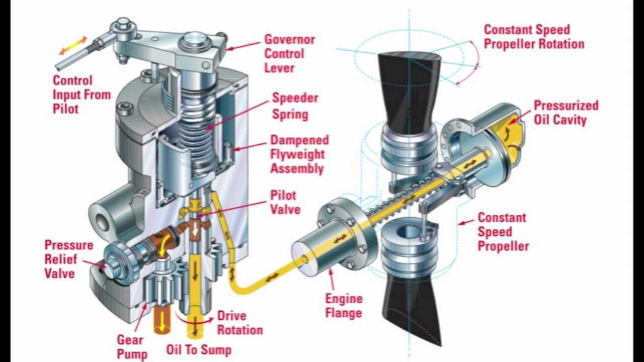
The constant speed propeller is controlled by the constant speed control unit attached to the side of the engine.
When the pilot opens the throttle the constant speed unit senses this change and coarsens the blade to absorb the extra power.
If the airspeed changes, the constant speed unit will also adjust the blade angle to absorb the changes in load on the engine. If the nose is lowered and the aircraft speed increases the propeller will increase. If the nose of the aircraft is raised the load on the engine will increase and the constant speed unit will fine the blade off.
22.24.8
Explain the purpose of the constant-speed (variable pitch) propeller.
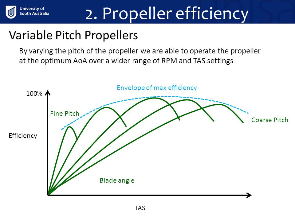
A constant speed propeller attempts to maintain the most efficient angle of attack over a wide speed range.
22.24.6
Explain how propeller pitch affects efficiency at different speeds.
As aircraft velocity increases, the angle of attack seen by the prop blade of a fixed-pitch prop will decrease. That effect limits the maximum efficiency of a fixed pitch prop to a single airspeed at a given RPM.


22.24.4
Describe the forces acting on a propeller blade; the rpm/airspeed relationship; and the most effective blade sections.
The forces acting on a propeller include thrust and torque. These are resolved from the total reaction. Torque is the resistance to rotation of the propeller and thrust is the driving force that is pulling the aircraft through the air.


The RPM/ airspeed relationship is such that as airspeed increases, the angle of attack of a fixed pitch propeller blade at a constant rpm will decrease. At some high airspeed, the angle of attack will reduce to the point where little or no thrust will
be produced. Hence for a given rpm there will only be one forward velocity at which the fixed pitch propeller will operate at it’s most efficient angle of attack.
The most effective section of a typical fixed pitch propeller is typically 75% of the chord of the blade.
This is the point where the angle of the blade is measured.
22.24.2
Define blade face, blade angle, pitch (or helix) angle, helical twist, angle of attack.
Define
|
The blade face is the back side of the blade and the blade angle is the angle of the blade compared to the plane of rotation. |
| Helix angle |
is the angle from the plane of rotation to the angle of attack |
| Helical twist |

is the twist the blade has from root to tip. This is done to maximise the efficiency of the propeller. |
|
|
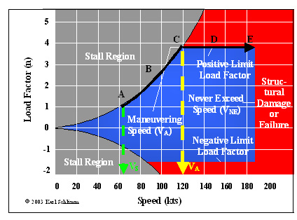
Va also known as manoeuvring speed is the maximum speed at which full and complete control movements can be used.
Va is the point on the diagram where the stall line meets the structural limits of the aircraft. See the yellow line on the diagram
Va is a variable speed based on the weight of the aircraft. As the aircraft gets heavier, Va increases. This is because the stall speed goes up as weight goes up and this moves the stall line on the diagram to the right, increasing Va
22.22.22
Describe design manoeuvre speed (Va) and explain the features of a typical V-n (or V-g) diagram.

Va also known as manoeuvring speed is the maximum speed at which full and complete control movements can be used.
Va is the point on the diagram where the stall line meets the structural limits of the aircraft. See the yellow line on the diagram
Va is a variable speed based on the weight of the aircraft. As the aircraft gets heavier, Va increases. This is because the stall speed goes up as weight goes up and this moves the stall line on the diagram to the right, increasing Va
22.22.20
Identify the factors affecting the radius of a looping manoeuvre.
The radius of the loop will be proportional to V2/’g’ (TAS/load factor).
The radius of the manoeuvre increases with the square of the speed.
A high load factor and a lot of altitude will be required to affect recovery
This relationship becomes important when recovery from a dive is considered, especially at low altitude.
22.22.18
Describe the forces acting during a maneuver in the looping plane

22.22.16
In climbing and descending turns, describe:
(a) the effect on rate of climb/descent;
(b) the tendency to overbank/under-bank.
(a) A climbing turn requires a tilted lift vector and increased lift to provide the centripetal force needed to turn. There is an increase in drag as well as lift. To offset this increased drag and maintain climbing speed, some of the excess power
being used in the straight-ahead climb is absorbed by the turn. With less excess power available for the climb, the rate of climb is reduced. This also means the nose attitude will be lower due to reduced climb performance.
If a constant speed is maintained the reduction in climb rate in the turn is proportional to the angle of bank used. Eventually an angle of bank will be reached where all the excess power is being absorbed by the turn; the rate of climb will be then reduced
to zero and the aircraft will be in a level turn.
The ability of an aircraft to climb and turn at the same time depends on the amount of excess power available at the climbing speed.
(b) There is a tendency for an aircraft to overbank in a climbing turn and under bank in a descending turn.

 https://vfr.nz/pic/briefings/TurningClimbing.svg
The tendency to overbank is caused by the outer wing having a higher effective angle of attack than the inner wing. Both wings travel the same vertical distance in the climb, but the outer wing travels on a wider arc and therefore a greater horizontal
distance.
This tendency can be quite pronounced in some aircraft so there is a need to ‘hold off bank’ to prevent the bank angle from increasing.
Insert image – Figure 11-15 Waypoints
In a descending turn there is a tendency to under bank, so the aircrafts inner wing has a higher angle of attack and will eventually roll out of the turn. Similar to the overbanking tendency, but the effect of the outer wing travelling through a greater
horizontal distance is reversed.
Insert image – Figure 11-16 Waypoints