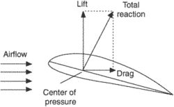
Total Reaction
- 2 components – lift and drag
- Depends on the efficiency of the wing / aerofoil / shape
- Acts through the CP (Centre of Pressure)
- Lift acts at right angles to the RAF
- Drag acts perpendicular to RAF
The TR can be resolved into lift and drag. The drag is induced drag and its scale is related to the tilting of the total reaction. The further back the total reaction is tilted, the higher the induced drag. As can be seen as the aircraft approaches the stall, the total reaction will be further and further tilted back meaning higher induced drag.
The lift is also a product of the total reaction. The higher the total reaction the higher the lift will be.
22.6.22
Describe how TR varies with increasing angle of attack ().
The higher the angle of attack the further aft the total reaction is tilted. Because it is always perpendicular to the chord line. As the total reaction is tilted aft the amount of induced drag rises. This means that the slower the aircraft flies the higher the induced drag because the higher the angle of attack. TR is almost vertical at smaller angles of attack and therefore induced drag will be at it’s lowest at high speed.
22.6.20
Define the total aerodynamic reaction force (TR) of an aerofoil;
We have to have an understanding of this concept for later study on lift and drag forces around the aerofoil
The force of lift is being exerted upward while the force of drag is being applied in a rearward direction. These forces are not equal, nor are they in opposite directions where one could possibly overtake or cancel the other. Therefore, they combine to make a total reaction that is applied in a direction relative to the strength of the individual forces.
Thi higher the angle of attack the further aft the total reaction is tilted. Because it is always perpendicular to the chord line. As the total reaction is tilted aft the amount of induced drag rises. This means that the slower the aircraft flies the higher the induced drag because the higher the angle of attack

22.6.18
Explain the term centre of pressure (CP); and describe typical movement of the CP with increasing angle of attack ().
As can be seen from the diagram below the centre of pressure, blue arrow moves progressively forward as the angle of attack is increased. Until the critical angle is reached. Once this angle is passed the centre of pressure moves rapidly aft at this point once lift breaks down

22.6.16
Explain the terms upwash and downwash in an airflow.
As the air approaches the leading edge of the wing most of it is swept up over the wing. This is known as upwash.
Air flowing off the rear of the wing is known as downwash as it is drawn into the void below the wing. This void causes the air over the top of the wing to be accelerated reducing pressure further.

22.6.14
Explain the changes to the airflow and pressure distribution around a typical aerofoil in a low- subsonic speed airflow as  is increased from the zero-lift angle to beyond the stalling angle.
Pressure distribution around the wing changes with angle of attack, as can be seen in the diagram below. Above 14° angle of attack lift breaks down and no longer can fully support the weight. At this point the aircraft is ‘stalled’ and will descend and the nose will pitch down

22.6.12
Describe a venturi and explain venturi effect.
We should understand the venturi principle as it’s an important principle for lift, instrument vacuum supply and aircraft carburettors.

A venturi can be thought of as a converging, diverging duct. This means at the entrance the duct is convergent i.e. it is getting smaller the further into the venturi. It then becomes a divergent duct. Which means it will get larger from the smallest point.
With this convergent divergent duct as can be seen in the diagram above the pressure in the ‘throat’ of the venturi is lower than the outer part of the venturi. This phenomenon has several uses. Air flowing over the wings obey this principle. The suction venturi which powers vacuum instruments on older aircraft also uses this principle as do carburettors on aircraft engines. The smallest point on the duct is used to draw fuel into the airflow so combustion can take place later in the cylinders of the engine.
22.6.10
State Bernoullifs theorem in simple terms, and describe streamline flow, turbulent flow,
and the application of Bernoullifs theorem to the streamline flow around an aerofoil.
Bernoulli’s theorem is an important concept related to the production of lift. We have to understand this to help understand the production of lift.

Bernoulli’s theorem states that the decrease in a pressure occurs at the same time as it’s velocity increases. Energy remains constant throughout the changing speeds and pressures

Streamline flow is flow that is straight and undisturbed. It flows evenly without disturbance. Turbulent flow has eddies in it and drag is caused. In a river streamline flow will look clear. Turbulent flow will have eddies and will seem to swirl around.

Bernoulli’s theory applies to aerofoils. As air flows over the top of the wing its speed increases, which according to Bernoulli’s theorem states that an increase in speed will cause a reduction in pressure. It can be shown that there is an increase in speed across the top of the wing and therefore pressure over the top of the wing is reduced. This is the basic principle of lift.
22.6.8
Define relative airflow and angle of attack ().
We need to understand relative airflow and angle attack so we can understand how the airflow affects the wing in flight.
Relative airflow is way we define how the air is flowing onto the wing. It can come from a variety of angles,depending on the portion of flight the aircraft is in. i.e. straight and level flight or a descent.
Angle of attack is the angle between the chord line and the relative airflow. The chord line being an imaginary line between the leading edge and trailing edge.

22.6.7
Distinguish between high-lift, general purpose (GP) and high-speed aerofoil sections.
Knowing about different aerofoil types will assist us in understanding why a certain type of aircraft performs the way it does.
High lift wing sections are used where the aircraft required large amounts of lift at relatively low airspeed i.e. a fletcher used for topdressing. General purpose aerofoils are used where a good compromise between speed and lift is required i.e. a Cessna 172 and high speed aerofoils are used where speed is the most important aspect of the flight i.e. a Boeing 787
All these aerofoils have quite different shapes that are optimised in a wind tunnel for their specific purpose.


