22.16.4
Explain basic stall speed and relate it to the lift formula.
The basic stall speed of the aircraft is the speed at which it can no longer maintain level unaccelerated flight, with the flaps up and the throttle closed.
Lift=CL1/2ρV2S
Ignoring (S) because we can assume wing area to be fixed, we can say
lift=Angle of attack X Airspeed
This means we can say that at the stalling airspeed the angle of attack will be at maximum.
Any increase in angle of attack will cause lift to reduce, which will mean the aircraft will start descending and the aircraft will ultimately stall.
22.16.2
Explain the stalled condition of an aerofoil.
When an aircraft stalls the amount of lift a wing can generate is substantially reduced. The wing can generate lift up until an angle of approximately 15-16° angle of attack. At this point the airflow is no longer able to smoothly flow over the wing and the lift production reduces. The CP moves rapidly aft and the aircraft will then usually pitch nose down.
This helpful for us because we can therefore work out when the aircraft will stall and why.
22.14.22
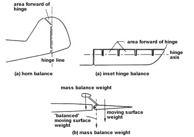
Describe the methods of providing mass balance.
Mass balancing can be achieved in a number of ways.
The first is to put the mass in the horn balance. This is a convenient place for it and it is out of the airflow.
The second is to put it forward of the hinge line of an inset hinge line control surface. This is common on an aileron.
The final method is to use an external mass balance that is exposed to the airflow and is forward of the hinge line. This method has the highest drag.
22.14.20
Describe and explain flexural and torsional flutter.
All structures bend and twist under load; the wings and fuselage will bend and twist the same as any other structure. It is noticeable on most large transport aircraft. The wingtips can move several metres. Even in small aircraft the structure will move to some extent, even though it may not be noticeable.
If a wing is subject to a transient upward and downward bending motion, maybe due to turbulence, aileron flutter may occur if the centre of gravity of the control surface is some distance behind the hinge line and because of inertia it lags behind the outer wing in it’s movement up and down. When this happens the changes in camber of the outer wing, which are caused by the lagging aileron magnify the flexing of the wing caused by the original oscillation and may make it self generating also known as flutter. This is called flexural aileron flutter.
The other affect that can occur is that the wing twists about the torsional axis, this is called aileron reversal. As the aileron is moved down to raise the wing, the upward force at the rear of the outer wing can cause the leading edge to twist downward such that the overall angle of attack of the outer wing is reduced. The effect will be the opposite on the other wing and this will cause the aircraft to roll in the wrong direction.
Aileron reversal can be reduced by making the wings torsionally strong enough – and another common method used in large transport aircraft is to use spoilers for roll control at high speeds.
22.14.18
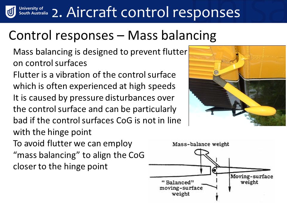
Explain the purpose for mass balancing.
Mass balancing is necessary on control systems that are prone to flutter. This is done by adding mass forward of the hinge line to bring the centre of gravity at or close to the hinge line. This decreases the tendency for the control surface movement to lag behind any flexural movement of the wing, reducing the risk of flutter.
22.14.16
Differentiate between a balance tab and an anti-balance tab.
There is a difference between balance and anti-balance tabs. Balance tabs provide a reduction in the load the pilot feels. Anti-balance tabs actually enhance control feel.
Anti-balance tabs are a feature of the “Stabilator” or full flying tailplane. As the CP of the control surface is very close to the hinge line there is very little control feel when moving the controls. The anti-balance tab provides this feel.

22.14.14
Describe the main methods for achieving control balance.
qThe main methods of achieving control balance are, Inset hinges, Horn balance and Balance tabs
Inset Hinges are a method of balancing control surfaces where the hinge line is moved behind the control surface leading edge. This reduces the distance between the hinge line and the CP, this will mean the control forces will be reduced. Also because of the position of the hinge, the leading edge of the surface will be deflected into the airflow when moved by the pilot. The airflow accelerates around the nose of the control surface when it protrudes which causes a decrease in pressure in that area which results in the Cp of the control surface moving further forward, reducing the moment arm. This is effectively an aerodynamic force acting ahead of the hinge line which helps to keep it deflected.
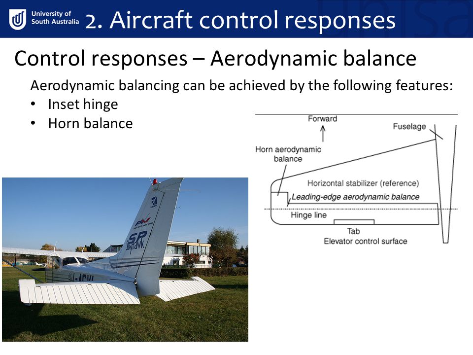
Horn Balance is achieved when a control surface is designed such that a portion of the surface protrudes ahead of the hinge line. The horn can be shielded or unshielded. Both types work on the same principal as the inset hinge line. As it is ahead of the hinge line it’s effect is to move the CP of the surface closer to the hinge line.
The designer must be careful not to bring the CP to close to the hinge line as this will reduce control feel, possibly to the point where the aircraft is unflyable. If the CP moves forward of the hinge line control reversal may happen. This is known as aerodynamically overbalanced.
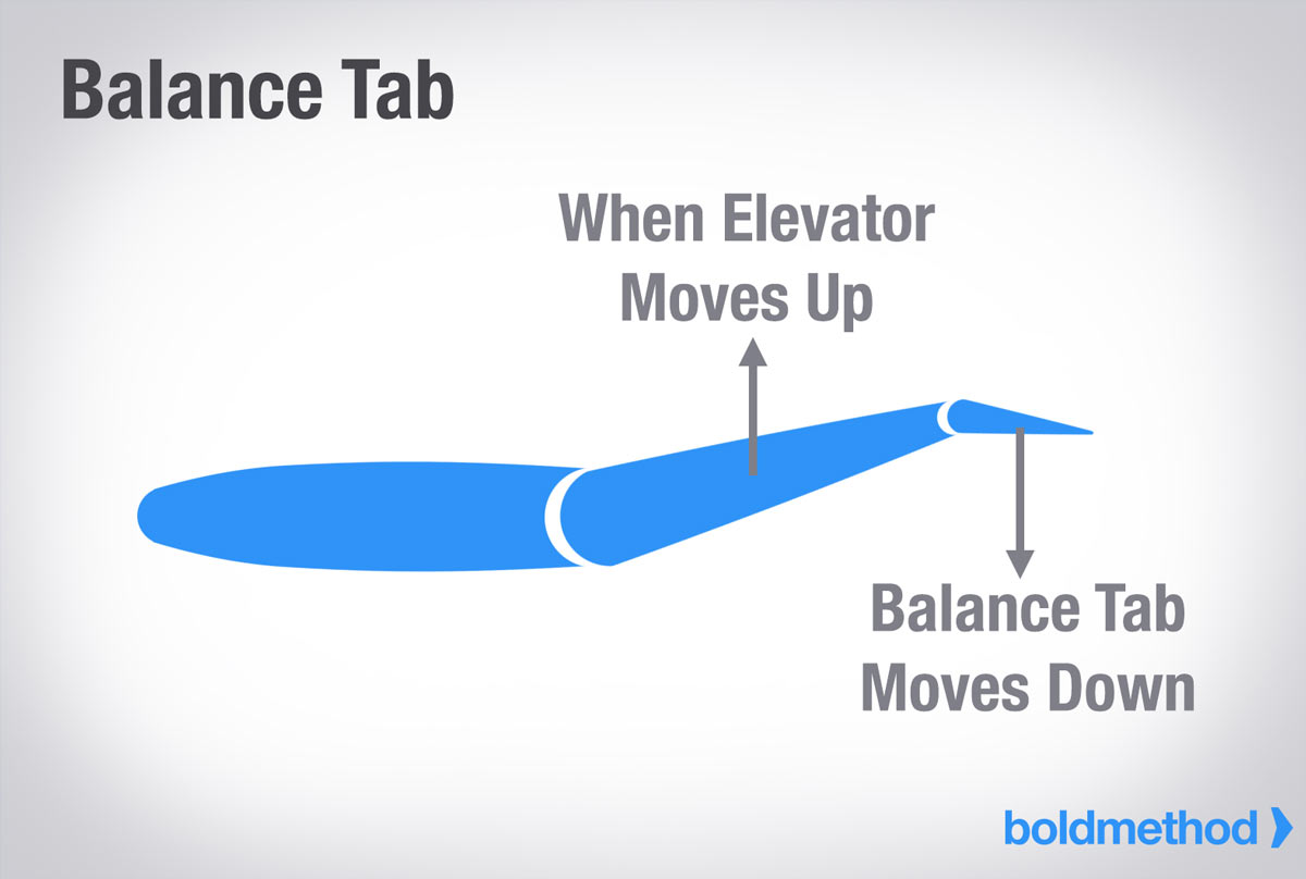
Balance tabs are a feature of conventional tailplanes. It is sometimes incorporated as a part of the elevator. It is set up so that when the elevator moves it will move in the opposite direction.
If the pilot moves the control column back and raises the elevator the balance tab moves down. This generates a small upward force that helps move the elevator up. This reduces the control force required by the pilot.
22.14.12
Explain the reason for aerodynamic balancing of control surface
Deflecting a control surface such as the elevator will cause a force in the opposite direction that opposes it’s deflection. This will cause a moment to act about the hinge line which tries to return it to it’s original undeflected position. The pilot has to add pressure against this force to overcome it and feels this as stick force.
The force produced by the deflected control surface acts through the centre of pressure of that control surface The greater the distance between the CP of the surface and the hinge line the greater the stick force
By altering the design of the surface it is possible to control the forces imparted to the pilot, methods for providing aerodynamic balancing include the use of inset hinges, horn balances and balance tabs
22.14.10
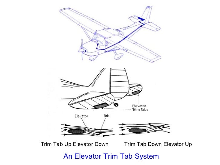
Explain the basic principles of trim tabs, and describe the correct method of using trim controls.
Trim tabs are used to balance flight control loads. Moving the trim tab will relieve flight control pressures for the pilot.
If the pilot is holding forward pressure on the control column the they will need to move the trim up – or forward in the case of electric trim which will relieve pressure. If the pilot is holding back pressure they will need to trim down or back to relieve pressure.