22.18.8
For unaccelerated level flight:
(a) state the power required formula (Power = Drag x TAS);
(b) explain the difference between the drag curve and the power required curve;
(c) distinguish between the minimum drag speed and the minimum power speed.
(a) Power required = drag X TAS
(b) The drag curve which also represents thrust required, is the total drag of the aircraft based on the airspeed of the aircraft. As parasite drag is low at low airspeed and induced drag is high, there is a point on the curve where drag is at the minimum. The power required curve is the total power needed to maintain level flight at that TAS
(c) Minimum drag speed is the point on the graph where drag is the lowest. This is the maximum range speed. The minimum power speed is the lowest power required on the graph. This is the maximum endurance speed.

22.18.6
Explain the power and attitude relationships at various airspeeds in straight and level flight.
Attitude + Attitude = Performance
[vfr_Insert p1=”S/LPowerAttutude”]
[vfr_Insert p1=”LiftSlow”]
22.18.4
For a conventional aeroplane configuration, describe:
(a) the lift/weight and thrust/drag couples;
(b) pitching moments and the tailplane stabilising moment;
(c) pitching moments caused by power changes, undercarriage and flap extension.
(a) The lift and weight are coupled through the aeroplane with a moment arm, this arm will cause the aircraft to pitch down generally.
The thrust drag couple also acts through the aircraft via a moment arm. This couple will cause the nose to pitch up.


(b) The tailplane provides a down force which balances the lift weight couple meaning the aircraft can maintain straight and level flight.

(c) Changing power will cause the aircraft to pitch. Increasing power will cause a nose-up pitching moment and reducing power will cause a nose-down pitching moment.
Lowering the undercarriage will cause a nose-down pitching moment, as will lowering the flaps on a low wing aircraft. Lowering the flaps on a high wing aircraft will cause a nose up pitching moment.

22.18.2
Explain the four forces acting and the conditions required for steady straight and level flight.
There are four forces acting on the aircraft in level flight. This is useful to us as it will help us understand what is happening when we fly the aircraft.
[vfr_Insert p1=”S/LForcesExplained”]
Describe the characteristics of the upright spin, and explain:
(a) the instrument indications which confirm the fact and direction of a spin;
(b) the difference between the spin and spiral dive;
(c) the standard recovery technique.
Once the aircraft has made approximately one turn it will be established in a spin.
The aircraft will be yawing, rolling and probably pitching too.
(a) Instrument indications
- The airspeed will be low
- The altitude will be reducing rapidly
- The ball will be indicating the direction of the spin
(b) There is a difference between the spin and the spiral dive.
In the spiral dive the airspeed will be steadily increasing; a spiral dive is really just a steep descending turn
In the spin the airspeed is low
(c) The standard recovery technique for a spin is
Power, reduced to idle
Ailerons neutral
Rudder, full opposite rudder against the direction of spin
Elevators, Check well forward to break the stall.
Once airspeed is increasing roll the wings level and recover to level flight
DO NOT roll wings level and pull out of the dive at the same time. This will cause rolling G which may damage the aircraft. these two actions must be done separately.
22.16.22
Explain the process of autorotation (leading to the spin).
Autorotation is when the aircraft starts rolling in an uncontrolled way. This is the precursor to the spin.
When the aircraft stalls, one wing will stall before the other and will end up more deeply stalled, even though both of the wings are stalled. This will cause the aircraft to roll. At this point the further effect will take place and the aircraft will start to yaw. This is self-sustaining and will get worse and worse. At this point because the aircraft has stalled the nose will also pitch down. The aircraft will be pitching, rolling and yawing all at the same time.
This will quickly develop into the spin.
22.16.20
Describe the standard technique for recovery:
(a) from a stall which has resulted in a wing-drop;
(b) at the onset of the stall.
(a) When an aircraft has stalled and the wing has dropped the standard recovery is as follows
- Check forward to reduce the angle of attack
- ensure the ailerons are centralised
- Stop the yaw with rudder
- Apply full power
- once the aircraft has some speed raise then set nose to the climb attitude
(b) At the onset of the stall
- Check forward to reduce angle of attack
- Apply full power
- control any resulting yaw with rudder
- set the nose to the flying attitude as soon as the aircraft has accelerated
22.16.18
Explain the caution against using aileron near or at the stalling angle
Using aileron at or near the stall will generally aggravate any wing drop tendency. The aircraft can actually enter autorotation and eventually a spin.
This is because of the increase in drag caused by the downing aileron compared to the upgoing aileron.
22.16.16
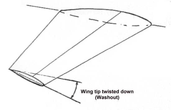
Explain the design measures taken to reduce the tendency for wing-drop.
There are several measures that can be taken to reduce the tendency for a wing drop.
The one used most often is washout. The angle of incidence is reduced towards the tip. This will cause the inboard section of the wing to stall first, minimising wing drop
Another method being used is to split the wing in two and have the outer section of the wing at a different angle of attack, the effect is the same except aileron control will be retained for longer.

The other common method of reducing the tendency of wing drop is that the aircraft can be fitted with stall strips on the inboard leading edges. This will cause the inboard section to stall first.

22.16.14
Describe the conditions which encourage a wing-drop at the stall.
Adding power and flap will destabilise the stall, possibly causing a wing drop.
Yawing and/or rolling the aircraft will also cause a wing drop stall.