22.10.30
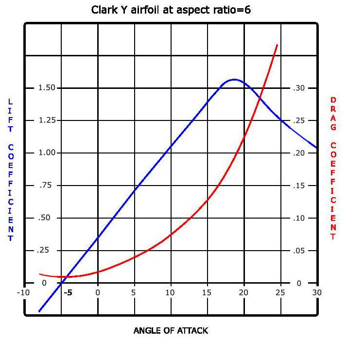
Explain from a typical graph the most efficient angle of attack, the zero lift position, and the stalling angle.
qAs can be seen from the graph below, the typical figures for a general aircraft aerofoil that the most efficient angle of attack is approximately 4° angle of attack as this is the biggest difference between lift and drag. The zero lift position is -5° and the stalling angle is about 16°
22.10.28
Explain a typical graph for lift/drag (L/D) ratio versus α
The lift/drag curve shows how the ratio functions relative to angle of attack. As can be seen, L/D ratio increases almost linearly to about 5° angle of attack. then it reduces steadily until the stall angle then it rapidly drops off.

22.10.26
Distinguish between graphs for CD and total drag.
q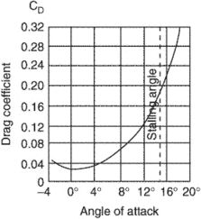

22.10.24
From information provided or a diagram identify the speed for minimum drag and maximum lift/drag ratio.

22.10.22
Describe typical curves of induced drag, all other drag, and total drag versus IAS in straight and level flight.
Induced drag decreases as speed increases. Parasitic drag increases as speed increases and total drag has a minimum point as can be seen in the diagram.
22.10.20
State the drag formula, and the three basic functions contained within it.
Drag=CD1/2ρV2S
CD Coefficient of drag
1/2ρV2 IAS
S Surface area of the wing
This formula is identical to the lift formula. The only change is CD
22.10.18
State the meaning of the term coefficient of drag (CD); and describe the main features
The drag coefficient (CD) is a non-dimensional parameter, but it takes into
account every aerodynamic configuration aspect of the aircraft including large
components as wing, tail, fuselage, engine, and landing gear; and small elements such as
rivets and antennae.
The drag coefficient of any object comprises the effects of the two basic contributors to fluid dynamic drag: skin friction and form drag. The drag coefficient of a lifting airfoil or hydrofoil also includes the effects of lift-induced drag. The drag coefficient of a complete structure such as an aircraft also includes the effects of interference drag.
22.10.16
Explain the origin of induced drag; and
(a) list the factors affecting it;
(b) explain typical measures for reducing it.
- Associated with the production of lift
- Arises from the downwash induced by the wingtip and trailing edge vortices
- Affected by Aspect ratio and Wing planform shape and
- Coefficient of lift; Angle of attack, Airspeed and Weight
- Reduction measures include washout combined with taper, wing fences and wing tip modifications
Induced drag is caused because the total reaction is tilted further rearwards. This creates a rearward component of total reaction that is induced drag, see the diagram below.
Π= a fixed ratio 3.14
AR= aspect ratio
Aspect ratio The higher the AR the nearer the wing will be to infinitely long. Higher aspect ratio wings produce smaller vortices. The induced downwash angle is smaller and induced drag will be lower.
Wing planform shape For a given wingspan the elliptical planform produces the smallest votaries and therefore the lowest induced drag. Most straight wings produce between 5 and 15% more induced drag than an elliptical wing.
Coefficient of lift For the pilot AR and planform shape are fixed, so the ways the pilot can control induced drag is with angle of attack, airspeed and aircraft weight. These are incorporated in the CL2 factor, which as the above equation shows has a powerful effect on the induced drag generated.
- Angle of attack Induced drag increases as the angle of attack increases. The strength of the vortices are dependant on the pressure difference above the and below the wing. When the wing is at the zero lift angle of attack there are no vortices and therefore no induced drag. Induced drag increases with an increase in angle of attack and will be at maximum at the stalling angle of attack.
- Airspeed Induced drag is inversely proportional to the square of IAS. Induced drag is greatest at low airspeed and lowest at high airspeed.
- Weight Increased weight means an increase in angle of attack to support the weight at any given airspeed. Therefore induced drag is proportional to weight squared (w2)

Washout and taper……
22.10.14
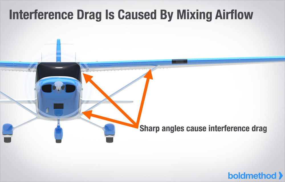
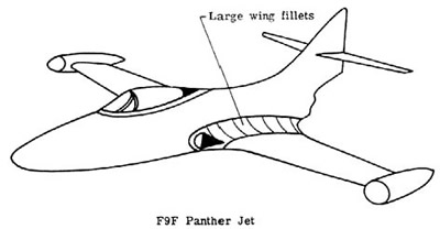
Describe interference drag and the measures for reducing it.
- Component of Parasitic drag
- Interference of converging airflows at the junctions of various surfaces
- Reduced by blending or filleting of surfaces
Interference drag is drag that is generated by the mixing of airflow streamlines between airframe components such as the wing and the fuselage, the engine pylon and the wing.
Interference drag can be reduced by carefully controlling the angles at which surfaces meet each other. It is also controlled by fairings to smooth the flow of air between to opposing surfaces.
22.10.12
Describe the effect of streamlining in reducing form drag.
- Reduces form drag by reducing adverse pressure gradients
- Delays separation, reducing the size of the turbulent wake and pressure differences
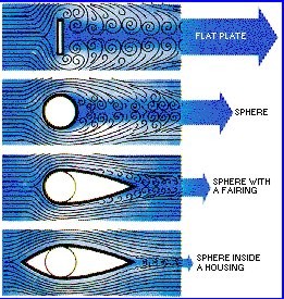
Streamlining effectively reduces form drag by smoothing the airflow behind the object.
Fineness ratio…….

