22.8.8
Given a typical CL versus Angle of Attack curve for a GP (general purpose)-type aerofoil, identify:
(a) the zero lift angle;
(b) the angle for maximum CL (CLmax).
- X-axis = Angle of Attack
- Y axis = CL
- Zero lift = Less than zero
- Max CL = Top of curve (Approximately 15˚)
CL vs Angle of Attack Graph for GP type (Cambered) Wing

For a typical training aircraft airfoil the zero lift is typically -4˚
The angle for maximum angle of attack is usually around 16˚
22.8.6
Describe the meaning of the term, coefficient of lift (CL).
Coefficient of lift is a number derived in a wind tunnel, factoring:
- A given shape of wing
- Angle of Attack
This gives us as pilots an indication of the amount of lift created by an aerofoil.

22.8.4
State the lift formula, and the three basic functions contained within it.
The Lift formula is Lift=CL1/2 ρ v2 S
This can be broken down to:
- CL is Angle of Attack for a given shape of wing
- 1/2 ρ v2, which for all practical purposes is IAS.
- S is the surface area of the wing
Therefore we can deduce, from the pilots point of view the formula becomes:
LIFT=ANGLE of ATTACK X AIRSPEED
22.8.2
Identify the factors affecting lift (low-subsonic speed airflow)
The size of the total aerodynamic reaction depends on a number of factors, these are
- Freestream air density
- Freestream velocity
- Size of the wing: in aerodynamics the plan form area used
- The shape of the wing, both in section and in plan form
- Condition of the surface, whether rough or smooth
- Angle of attack
In practice this can be reduced to three factors, as follows
- The free stream density and velocity are incorporated in the expression for dynamic pressure 1/2 ρ v2, which for all practical purposes is IAS.
- The effect of wing area is straightforward. Lift is produced as a result of the pressure differential above and below the wing. The greater the area a given pressure differential can act upon, the greater the lift produced.
- The remaining variables are combined into a single factor called the coefficient of lift (CL)
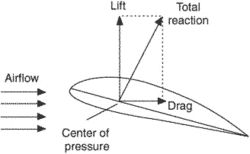
Total Reaction
- 2 components – lift and drag
- Depends on the efficiency of the wing / aerofoil / shape
- Acts through the CP (Centre of Pressure)
- Lift acts at right angles to the RAF
- Drag acts perpendicular to RAF
The TR can be resolved into lift and drag. The drag is induced drag and its scale is related to the tilting of the total reaction. The further back the total reaction is tilted, the higher the induced drag. As can be seen as the aircraft approaches the stall, the total reaction will be further and further tilted back meaning higher induced drag.
The lift is also a product of the total reaction. The higher the total reaction the higher the lift will be.
22.6.22
Describe how TR varies with increasing angle of attack ().
The higher the angle of attack the further aft the total reaction is tilted. Because it is always perpendicular to the chord line. As the total reaction is tilted aft the amount of induced drag rises. This means that the slower the aircraft flies the higher the induced drag because the higher the angle of attack. TR is almost vertical at smaller angles of attack and therefore induced drag will be at it’s lowest at high speed.
22.6.20
Define the total aerodynamic reaction force (TR) of an aerofoil;
We have to have an understanding of this concept for later study on lift and drag forces around the aerofoil
The force of lift is being exerted upward while the force of drag is being applied in a rearward direction. These forces are not equal, nor are they in opposite directions where one could possibly overtake or cancel the other. Therefore, they combine to make a total reaction that is applied in a direction relative to the strength of the individual forces.
Thi higher the angle of attack the further aft the total reaction is tilted. Because it is always perpendicular to the chord line. As the total reaction is tilted aft the amount of induced drag rises. This means that the slower the aircraft flies the higher the induced drag because the higher the angle of attack

22.6.18
Explain the term centre of pressure (CP); and describe typical movement of the CP with increasing angle of attack ().
As can be seen from the diagram below the centre of pressure, blue arrow moves progressively forward as the angle of attack is increased. Until the critical angle is reached. Once this angle is passed the centre of pressure moves rapidly aft at this point once lift breaks down

22.6.16
Explain the terms upwash and downwash in an airflow.
As the air approaches the leading edge of the wing most of it is swept up over the wing. This is known as upwash.
Air flowing off the rear of the wing is known as downwash as it is drawn into the void below the wing. This void causes the air over the top of the wing to be accelerated reducing pressure further.

22.6.14
Explain the changes to the airflow and pressure distribution around a typical aerofoil in a low- subsonic speed airflow as  is increased from the zero-lift angle to beyond the stalling angle.
Pressure distribution around the wing changes with angle of attack, as can be seen in the diagram below. Above 14° angle of attack lift breaks down and no longer can fully support the weight. At this point the aircraft is ‘stalled’ and will descend and the nose will pitch down

