22.6.12 Describe a venturi and explain venturi effect.

22.6.12
Describe a venturi and explain venturi effect.

We should understand the venturi principle as it’s an important principle for lift, instrument vacuum supply and aircraft carburettors.

                                       Image result for venturi and explain venturi effect.

A venturi can be thought of as a converging, diverging duct. This means at the entrance the duct is convergent i.e. it is getting smaller the further into the venturi. It then becomes a divergent duct. Which means it will get larger from the smallest point.

With this convergent divergent duct as can be seen in the diagram above the pressure in the ‘throat’ of the venturi is lower than the outer part of the venturi. This phenomenon has several uses. Air flowing over the wings obey this principle. The suction venturi which powers vacuum instruments on older aircraft also uses this principle as do carburettors on aircraft engines. The smallest point on the duct is used to draw fuel into the airflow so combustion can take place later in the cylinders of the engine.

22.6.10 Bernoullifs theorem

22.6.10
State Bernoullifs theorem in simple terms, and describe streamline flow, turbulent flow, 
and the application of Bernoullifs theorem to the streamline flow around an aerofoil.

Bernoulli’s theorem is an important concept related to the production of lift. We have to understand this to help understand the production of lift.

                                       Image result for venturi effect

Bernoulli’s theorem states that the decrease in a pressure occurs at the same time as it’s velocity increases. Energy remains constant throughout the changing speeds and pressures

                                       Image result for streamline flow, turbulent flow,

Streamline flow is flow that is straight and undisturbed. It flows evenly without disturbance. Turbulent flow has eddies in it and drag is caused. In a river streamline flow will look clear. Turbulent flow will have eddies and will seem to swirl around.

                       Image result for Bernoulli's theorem to the streamline flow around an aerofoil.

Bernoulli’s theory applies to aerofoils. As air flows over the top of the wing its speed increases, which according to Bernoulli’s theorem states that an increase in speed will cause a reduction in pressure. It can be shown that there is an increase in speed across the top of the wing and therefore pressure over the top of the wing is reduced. This is the basic principle of lift.

22.6.8 Define relative airflow and angle of attack ().

22.6.8
Define relative airflow and angle of attack ().

We need to understand relative airflow and angle attack so we can understand how the airflow affects the wing in flight.

Relative airflow is way we define how the air is flowing onto the wing. It can come from a variety of angles,depending on the portion of flight the aircraft is in. i.e. straight and level flight or a descent.

Angle of attack is  the angle between the chord line and the relative airflow. The chord line being an imaginary line between the leading edge and trailing edge.

                              Image result for relative airflow and angle of attack

22.6.7 Distinguish between high-lift, general purpose (GP) and high-speed aerofoil sections

22.6.7
Distinguish between high-lift, general purpose (GP) and high-speed aerofoil sections.

Knowing about different aerofoil types will assist us in understanding why a certain type of aircraft performs the way it does.

High lift wing sections are used where the aircraft required large amounts of lift at relatively low airspeed i.e. a fletcher used for topdressing. General purpose aerofoils are used where a good compromise between speed and lift is required i.e. a Cessna 172 and high speed aerofoils are used where speed is the most important aspect of the flight i.e. a Boeing 787

All these aerofoils have quite different shapes that are optimised in a wind tunnel for their specific purpose.

                                        Image result for high-lift, general purpose (GP) and high-speed aerofoil sections.

22.6.6 With respect to aerofoils, describe the meanings of the foll

22.6.6
With respect to aerofoils, describe the meanings of the following terms: section, leading edge, trailing edge, chord, chord line, thickness, thickness/chord ratio, camber.

Having an understanding of the terms used when describing aerofoils helps us because we know the correct terminology. This will make understanding later principles of the wing much simpler.

Below is a diagram explaining most of the important terms. The only one not described is thickness/chord ratio. This is simply the ratio of the maximum thickness of the wing to the total chord. 

Thickness/Chord.

                        Image result for leading edge, trailing edge, chord, chord line, thickness, thickness/chord ratio, camber.

22.6.4 Explain the principle of airspeed indication, and indicate t

22.6.4
Explain the principle of airspeed indication, and indicate the relationship between indicated, calibrated, equivalent and true airspeeds (IAS, CAS, EAS, and TAS).

Airspeed is one of the most important concepts in aviation. We must understand what it is and the various types of airspeed as well. 

Airspeed indication is a measurement of dynamic pressure entering the Pitot tube.

                      Image result for airspeed indicator diagram

Static pressure is fed into the case of the instrument which cancels out the effect of static pressure in the Pitot tube. This means Indicated airspeed is shown on the instrument.

Airspeed indicators are calibrated at ISA sea-level density conditions. It is only under these conditions that they will accurately indicate the actual airspeed (that is, the true airspeed or TAS) of the aircraft through the air. When the ambient (freestream) air density differs from standard sea-level conditions the indicated airspeed will be different from the actual airspeed. This difference (sometimes called density error) and other errors which arise in the airspeed indication system has given rise to a number of different terms for airspeed.

Indicated Airspeed (IAS)

IAS is the reading on the airspeed indicator (ASI). There may be some differences between the indications registered by individual ASI’s, but these instrument errors are usually so small they can be ignored.

Calibrated Airspeed (CAS)

CAS is IAS corrected for pressure (or position) error. Pressure error arises mainly from incorrectly sensing the total and static pressure when the aircraft is in different flight attitudes. When pressure error correction (PEC) cards are displayed in the cockpit, they include the instrument error correction for the particular ASI. In practice the PEC at normal cruise speed is so small and can under most circumstances be ignored

Equivalent Airspeed (EAS)

Most ASI’s are designed to measure dynamic pressure (1/2ρV2) on the assumption that air is incompressible. Air is compressible and as speed is increased the pitot tube will increasingly register higher pressure that it should be cause air becomes compressed. When CAS is corrected for the compressibility error becomes known as EAS

True Airspeed (TAS)

TAS may be obtained by dividing the EAS by the square root of the relative density i.e. the prevailing density as compared with the standard sea-level density. If the prevailing density sea level happened to be standard the relative density would be 1 and EAS would equal TAS. Flying at 40,000 ft under standard conditions where the relative density is one quarter of the sea-level value, the EAS would be half the TAS (the square root of ¼ is ½). In practice TAS is usually calculated by using a navigation computer.


22.6.2 Describe the terms freestream static pressure, dynamic press

22.6.2
Describe the terms freestream static pressure, dynamic pressure (including the term .V2) and total (or pitot) pressure.

These are important ideas that are used throughout our flying career. We have to understand the principles involved and apply them correctly to make full use of them.

Freestream static pressure is a term used in aerodynamics of the prevailing atmospheric pressure. The symbol ρ∞ is used to denote it. The term free stream indicates the air conditions that exist well ahead of a body moving through the air, as yet unaffected by it’s passage. The freestream static pressure decreases with altitude.

                                           Image result for air pressure around a body

When a solid body is moving that air pressure surrounding it will no longer be even. The surface pressures experienced by those areas facing into the airstream will be increased above the freeestream value, whereas the pressures to the side and the rear will generally be reduced. The differences in the pressure experienced are related to the kinetic(or Dynamic) energy the air has because it is moving and the extra pressure that it is capable of exerting as a result. This is called the Dynamic pressure.

               Image result for dynamic pressure

Any solid body that is moving has kinetic energy. This is calculated by:


                                                 kinetic energy = 1/2mV2

Air also has kinetic energy when it is moving, normally referred to in aerodynamics as dynamic energy. The mass of air is measured by it’s density. The symbol for density it the Greek letter ρ, pronounced RHO. If we substitute density for mass in the above equation, we can calculate that amount of dynamic energy in a moving mass of air.

                                              dynamic energy = 1/2ρV2

                                                           ρ = density

                                              V = velocity of the airstream

If this moving mass of air is stopped by a solid body and bought completely to rest, the dynamic energy it contains is converted to pressure energy. For this reason, the pressure energy that arises is called dynamic pressure and it is exerted on the body in addition to the prevailing static system.

                                             dynamic pressure = 1/2ρV2

The term 1/2ρV2  therefore stands for ‘the additional pressure imposed when air of a certain density moving at a given velocity is bought completely to rest’. It is also used in a more general way to describe the amount of dynamic energy contained in a moving airstream.

Very little of the air moving past an aircraft in flight is bought completely to rest. The term for dynamic pressure (1/2ρV2) is nevertheless very important; all aerodynamic forces are proportional to it.

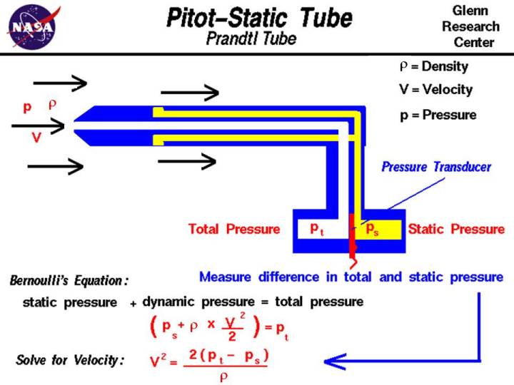
Dynamic Pressure is utilized in the measurement of airspeed. A small amount of air is bought to rest in a forward facing tube called the Pitot Tube. The pressure that is present inside the tube is called total (or pitot) pressure and it comprises the dynamic pressure caused by bringing the moving air to a rest plus the freestream static pressure.


                Total (or pitot) pressure = free stream static pressure + Dynamic pressure

                                                        =ρ∞ + 1/2ρV2

ρ∞ =Standard Sea Level Air Density

So to measure airspeed we need to work out the difference between total pressure and static pressure.

                Total pressure (dynamic + static) – static  = dynamic pressure

                which can be written as (ρ∞ + 1/2ρV2 ) – ρ∞ = 1/2ρV

The airspeed indicator (ASI) is simply a dynamic pressure gauge that is calibrated to read airspeed (knots)

            Image result for dynamic pressure


24.4.16 Explain the term viscosity, when related to air.

24.4.16
Explain the term viscosity, when related to air.

When air moves across a perfectly flat plane surface, the layer of molecules in immediate contact with that surface will be bought to a standstill (or nearly so) because of it’s viscocity (or stickiness). Successive layers of ait above that very bottom layer will be slowed down by decreasing amounts until the point is reached where the effect of viscocity is no longer felt.

24.4.14 Explain the meaning of density altitude (DA) and, in broad t

24.4.14
Explain the meaning of density altitude (DA) and, in broad terms, the effect of pressure, temperature and humidity on DA and thus aerodynamic and engine performance.

Density altitude is the altitude in ISA that has the same air density as the actual altitude

Pressure temperature and humidity all have an effect on density altitude.

Density altitude has a direct effect on aircraft performance, both aerodynamically and in terms of engine power

A high temperature will indicate low density and poorer performance

A low temperature will indicate high density and better performance

A high pressure will indicate high density and better performance 

A low pressure will indicate a low density and poorer performance

24.4.12 Describe the approximate altitude bands in which atmospheric

24.4.12
Describe the approximate altitude bands in which atmospheric pressure and density are reduced to 75, 50 and 25% of their normal sea level values.

75% sea level pressure    8-10,000 feet

50% sea level pressure   18-22,000 feet

25% sea level pressure   34-41,000 feet