4.80.4 State the requirement for the notification of incidents. CAR 12 [vfr_Rule p1=”12.55″]
The pilot-in-command, or if unable the operator, shall notify the Authority as soon as practicable.
Details of an incident must also be provided within 14 days of the incident
4.78.6 Describe aerodrome beacons.
4.78.4 Describe the following lighting systems:
a) Runway edge lighting (REDL);
(b) Runway landing threshold lighting (RTHL);
(c) Runway end lighting (RENL);
(d) Runway centreline lighting system (RCLL);
(e) Runway end identifier lighting (REIL);
(f) Circling guidance lighting (CGL);
(g) Runway lead in lighting (RLLS); and,
(h) Pilot activated lighting (PAL).
4.76.12 Interpret runway and taxiway signs and markings. CAR 139
- Runway markings must be white
- Taxiway markings must be yellow
- Apron safety lines must be a conspicuous colour which should contrast with that used for aircraft stand markings
- Runway turn pad markings and aircraft stand markings must be yellow
- Runway designation markings, centre-line markings and threshold markings must all be provided on paved runways
- At the intersection of 2 or more runways, the markings of the most important runway must be displayed. The markings of the other runway/s must be interrupted
- At the intersection of a runway and taxiway the markings of the runway must be displayed and those of the taxiway interrupted
- Holding points are marked on a sealed runway by yellow lines painted across the taxiway. There may be a board near the holding point with the name on it
- On unpaved taxiways the holding points will be marked by cones or marker boards
- On runway surfaces of light colour the conspicuity of white markings can be improved by outlining them in black
- Where operations take place at night, pavement markings should be made with reflective materials to enhance the visibility of the markings
- Unpaved taxiways should be provided with edge markings, boundary markers, cones or other markers to clarify the taxiway edge if not made obvious by surface texture or colour
- Runway centre line markings should be provided on all paved runways
- Centre line markings should be located along the centre of the runway between the runway designation markings (except when interrupted in compliance with runway intersections rules)
- Runway centre markings should consist of a series of uniformly spaced stripes and gaps
- Threshold markings should be provided at the threshold of the runway stripes, commencing 6 m from the threshold; made up of a pattern of longitudinal stripes of uniform dimensions symmetrically placed about the centre-line
4.76.10 Interpret information on aerodrome/heliport charts. AIP GEN & AIP Volume 4
Aerodrome/Heliport Charts include:
- Date effective
- ICAO location
- Elevation in ft
- Controlled airspace with vertical limits
- Co-ordinates
- Sector boundary of airspace,
- Natural high point with elevation
- Runway length and width
- Communications frequencies
- Controlled airspace with vertical limits
- Direction arrow
- VFR arrival and departure route
- Traffic circuits
- Any specific arrival / departure instructions
4.76.8 Describe the meaning of the various aerodrome ground signals.
AERODROME GROUND SIGNALS
 |
When displayed at a Parachute Landing Area (PLA), a red and white cone with the point of the cone pointing into wind indicates that the dropping area is active |
 |
A white Letter “A” indicates that agricultural operations or training operations are being conducted. These flight may not comply with the direction of the aerodrome circuit |
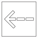 |
An arrow formed of white fabric strips on the surface indicates that Gliding is in progress.
Gliders are landing and being towed off in the direction of the arrow.
Tow lines are likely to be on the ground at any distance from the towing source and on or parallel to the signal strips |
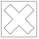 |
White crosses displayed horizontally on the manoeuvring area indicate that the ground or portion of runway is unfit for use |
4.76.6 Describe the movement area of an aerodrome. CAR 1
Movement area means that part of an aerodrome intended to be used for;
the take-off and landing of aircraft and for the surface movement of aircraft,
and includes the manoeuvring area, maintenance areas, and aprons.
4.76.4 Describe the method of runway designation. AIP AD
The runway or strip designation is a two-digit number based on
the whole number nearest to one-tenth of the magnetic azimuth
of the centre line when viewed from the direction of approach, e.g. if the magnetic azimuth of strip is 208°M, the runway will be designated as RWY 21
4.76.2 Describe the limitations on the use of a place as an aerodrome or heliport. CAR 91
- Aerodrome must be suitable for the aircraft taking off or landing.
- Must comply with any limitations and operational conditions for the aerodrome
- If operating at night, operable lighting is available and activated
- Runway is clear of all persons, animals, vehicles, vessels, or other obstructions other than persons, vehicles, or vessels essential to the operation.
4.75.32 Interpret airspace information on aeronautical charts used for VFR flights.
On Aeronautical charts
- Control Zones (CTR) have blue solid line boundaries / Class of airspace in the CTR and CTR upper limit / CTR – lower limit (SFC) /Whether Transponder Mandatory
- Control Areas (CTAs) on aeronautical charts – Purple boundaries with solid line / Class of airspace in the CTA / upper and lower limits (SFC) / (SFC) / whether Transponder Mandatory
- Mandatory Broadcast Zone airspace on aeronautical charts – Boundary is shown by a blue dotted line / Designated by the letters MZB / followed by 3-digit number and a name followed by a designating letter / frequency to use and the time interval at which position reports must be transmitted
- VFR Transit Lanes on Aeronautical charts; Boundary is solid blue lines / Letter “T“] followed by a 3-digit figure and a name, The word “DAY” is added to emphasize transit lane availability is daytime only
- Restricted Areas airspace on aeronautical charts – Restricted area shown in red / NZR, followed by 3-digit number and a name plus the time during which the area is active
- Military Operating Zones airspace on aeronautical charts / Restricted area shown in red / NZM followed by 3-digit number / the time during which the area is active H24 means permanently active
- Volcanic Hazard Zone airspace on aeronautical charts – area shown in red with upper and lower limits / NZV, followed by 3-digit number / H24 means permanently active volcano
- Low Flying Zone airspace on aeronautical charts – Shown by thin blue lines / NZL followed by 3 digit number and a name / upper and lower limits given.